Method and apparatus for the photo-acoustic identification and quantification of analyte species in a gaseous or liquid medium

a photo-acoustic and analyte technology, applied in the field of ultra-sensitive analysis of gaseous species, can solve the problems of low immunity, inability to find a single commercial gas detection product, and limited impact on the gas sensing industry, so as to improve the sensitivity, improve the sensitivity, and improve the effect of low-power laser radiation

Inactive Publication Date: 2012-12-11
LI COR
View PDF29 Cites 20 Cited by
  • Summary
  • Abstract
  • Description
  • Claims
  • Application Information

AI Technical Summary

Benefits of technology

[0023]the phase sensitive detection of the first harmonic of the first photo-detector signal is used for constant adjustment of the cavity length, such that the carrier wavelength of the laser is always in resonance with the cavity. This cavity locking scheme does not require dithering the cavity mirror position and thus provides strong uninterrupted error signal for the cavity lock loop;

Problems solved by technology

PAS has been among the methods of ultra-sensitive spectroscopy popular in scientific research, but to date it has had a very limited impact on the gas sensing industry.
Hz. However, the sensitive general purpose microphones used in PAS required elaborate acoustic isolation of the sample cells, and low immunity to ambient noise may be a reason impeding its use in noisy industrial environm
ensor size. Surprisingly however, even in 2009, seven years after the invention of QEPAS, one cannot find a single commercial gas detection product based
5-922 (1968). The explanation is simple—the power of the commercially available laser sources is too low, and therefore the limits of detection on concentration are non-competitive with
06)]. One can say that these acoustic resonance enhancement techniques have been generally optimized and that one cannot reasonably expect a further responsivity increase of no greater than several tens of per
d in QEPAS. This means that the detection threshold of both sensors cannot be further improved, and the only way to lower the NEA is to increase the excit
ation power. With semiconductor lasers operating in the C- or L-band telecommunication range the power can be increased to watts level by using an Erbium-doped fiber amplifier, [see M. Webber, et. al., Appl. Opt., 42 (12), 2119-2126 (2003)] but this solution has an unacceptab
ly high price. Another way to increase the excitation beam power by placing the photo-acoustic cell inside the resonant cavity of a laser is obviously not applicable to DFB semiconductor lasers, and it would not be practical even with an external cavity diode laser because the power buildup is rather small in the lossy cavities
irrors reflectivity. However, this work cannot be considered as showing encouraging prospects for building industrial gas OPBC-PAS sensors
ith no OPBC enhancement. A second important reason is that the method of locking the diode laser radiation to the cavity described in the Rossi paper was only marginally effective even in a perturbation-free
laboratory environment. The unstable and unreliable operation of the diode to cavity lock also resulted in very poor stability of the buildup intensity dependence as a function of time as one can see from FIG.
An unavoidable drawback of such approach is that the locking cannot be done during periods when the laser is off.
After the laser is turned on again, a large error signal results in over-reaction of the locking system, and the lock can be lost again because of this over-reaction.
As a result such systems have low immunity to external perturbations, high instability of the buildup power, and are essentially useless for applications in field useable systems.ii) Systems that constantly maintain a lock of the laser to the cavity, such as described in U.S. Pat. No. 7,263,871.

Method used


Image

  • Method and apparatus for the photo-acoustic identification and quantification of analyte species in a gaseous or liquid medium
  • Method and apparatus for the photo-acoustic identification and quantification of analyte species in a gaseous or liquid medium
  • Method and apparatus for the photo-acoustic identification and quantification of analyte species in a gaseous or liquid medium

Examples


Embodiment Construction

[0042]We now provide a detailed description of the method of the invention and several embodiments of the apparatus applicable to the method.

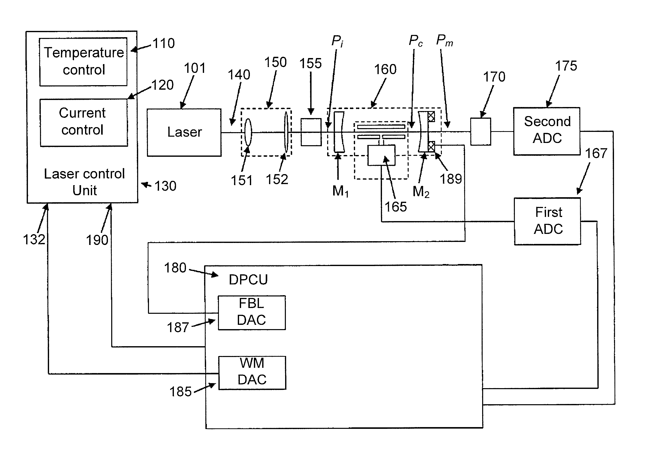
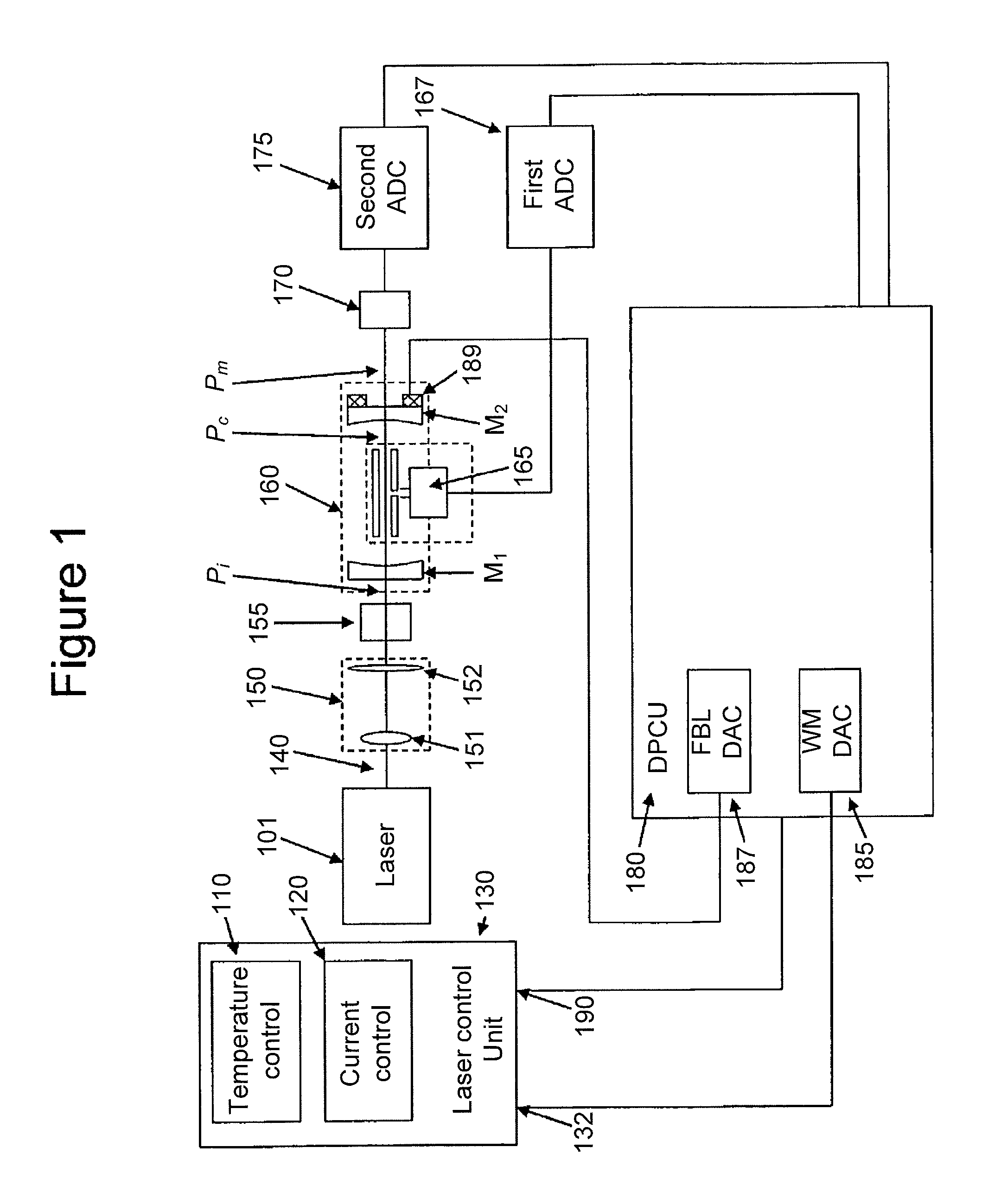
[0043]A schematic diagram of the gas detection system of the present invention is shown in FIG. 1. The present invention in a preferred embodiment contains a semiconductor laser source 101, preferably a distributed feedback (DFB) laser emitting a single emission line that can be tuned in the vicinity of the absorption line of the analyte species of interest within a range of several wave numbers. The operating wavelength of the laser can be changed or modulated, for example, by changing the operating temperature of the semiconductor laser chip, and / or its drive current. This is accomplished by electronic modules known in the art such as a diode laser temperature controller 110 and / or a low noise diode laser current controller 120. In other embodiments the laser can be of other known type subject to the requirement that its wavelength of operati...


PUM


Abstract

A method and apparatus for the photo-acoustic identification and quantification of one or more analyte species present in a gaseous or liquid medium in low concentration utilizing a laser and a resonant optical cavity containing the medium and having within the cavity at least two partially transparent mirrors, one of which is a cavity coupling mirror and one of which is moveably mounted on an assembly responsive to an input signal.

Description

BACKGROUND OF THE INVENTION[0001]This invention belongs to the field of ultra-sensitive analysis of gaseous species or more specifically, to spectroscopic methods of analysis such as, for example, Photo Acoustic Spectroscopy (PAS) that benefit from a high intensity light source. PAS has been among the methods of ultra-sensitive spectroscopy popular in scientific research, but to date it has had a very limited impact on the gas sensing industry. Many years of PAS research as an analytical method has resulted in a general understanding of the nature of the photo acoustic effect and of a suitable configuration for photo acoustic cells. Classical PAS (a microphone and a resonant acoustic cell) have reached a high level of operating performance. As evidence of such is the fact that the best results demonstrated in recent years by different groups e.g., [A. Miklos, et. al., Rev. Sci. Instr., 72(4), 1937-1955 (2001); M. Webber, et. al., Appl. Opt., 42(12), 2119-2126 (2003) and V. Kapitanov...

Claims


Application Information

Patent Timeline
Patent Type & Authority Patents(United States)
IPC IPC(8): G01N21/00
CPCG01N21/1702G01N21/39G01N2021/1704H01S5/005H01S5/0064H01S5/0656G01N2021/1708
Inventor KACHANOV, ALEXANDERKOULIKOV, SERGUEI
Owner LI COR
Why Eureka
Try Eureka