System and method for liquid treatment

Inactive Publication Date: 2013-07-02
EAST COAST DISTRIBUTION
8 Cites 25 Cited by

AI-Extracted Technical Summary

Problems solved by technology

However, mercury UV lamps have a long warm-up period (at least a few minutes), which increases the startup time of operation, and the lamps cannot be operated in a pulsed mode.
Mercury UV lamps cannot be turned on immediately after the shutdown, making it difficult to continue their operation after an unscheduled shutdown.
There are major problems with their disposal; they are not environmentally friendly, it is necessary to control the mercury vapor level, the lamps must be transported in special containers, and mercury cleaning in the event of damaged lamps is an additional expense.
However, the maximum ozone production rate is very low; namely, maximum concentration of ozone that can be produced by 185-nm UV lamp is 0.2 percent by weight, approximately 10% of the average concentration available by corona-discharge.
However, the existing barrier discharge ozone generators are expensive; they require a large area for their installation, and they require a powerful high voltage source.
Corona-discharges result in a fast deterioration of the dielectric barrier.
The ozone generators consume a large amount of electrical power.
These generators ...

Method used

[0078]The two inactive ends 9 of the lamp 1 may be made of a material with the same coefficient of linear thermal expansion (CLTE) as that of the active synthetic quartz inner 3 and outer 2 sleeves. The material of the ends 9 may have UV transmission characteristics different from those of the sleeves 2 and 3, or it may block radiation in UV range of spectrum altogether (or does not have capability for UV transmission at all). The use of different materials for the manufacturing of active sleeves 2 and 3 and inactive ends 9 of the lamp 1 is innovative, it provides cost savings and simplification the manufacturing procedure; making the production and assembly of the excimer lamp more straightforward, reliable and streamlined.
[0079]The material of the two inactive ends 9 of the lamp 1 may have a CLTE that is different from the CLTE of synthetic quartz used for the active inner 3 and outer 2 sleeves. For the purpose of compatibility, transition rings 9b (parts of a material, matching the CLTE of the material of the active sleeves with the CLTE of the material of the ends of the lamp, in the required amount) of an appropriate size and made of a material with an appropriate CLTE are used. Transition rings 9b are unique to this invention. Their advantages are a reduction of the production cost and the ability to automate the lamps manufacturing process and, consequently, significantly reduce the cost of the excimer lamp.
[0081]Solder areas 9d (the areas, which is used for connecting to a vacuum machine or a gas supply source, for technological testing of a lamp and filling the lamp with an excimer gas) may be located on inactive ends 9 of the lamp 1 and may have a CLTE different from that of the CLTE of active sleeves 2 and 3 of the lamp 1. The use of a CLTE of the solder areas that is different from the CLTE of the active surfaces of the lamp is unique to this invention. The advantages of this solution are an improved automation of the lamp's production, reducing defects in the manufacturing of the excimer lamps and a more effective quality control.
[0084]Two inactive ends 9 of lamp 1 may have a coating 9c that reduces their electrical conductivity compared to the main material ends 9 are made of. The advantage of using the coating 9c is the increased operating voltage of the excimer lamp 1 without the possibility of an electrical breakdown.
[0087]In the production of lamp 1, the material of all surfaces or parts thereof may be treated chemically, thermally, or otherwise in order to improve the operational characteristics of lamp 1 (increasing the life time, improving spectral transmission characteristics, mechanical stability, tolerance to the sign-variable mechanical force loads, the fluctuation of pressure of the operation, changes in temperature, chemical composition of the liquid being treated, and the external radiation of any wavelength).
[0088]During the filling phase of lamp 1 manufacturing, the method of desorption of the dissolved additives is used. The method involves the removal of water, dissolved gases, and other pollutants from the active surfaces of the sleeves 2 and 3 of lamp 1 by means of filling space 6 of lamp 1 with a special temporary liquid or/and gas mixture causing a short-term increased desorption from the internal surfaces of sleeves 2 and 3 during exposure of desorption mixture to a radiation in the range of the spectrum that is sensitive for the desorption mixture. This method is unique to this invention. The benefits of this method are as follows. It assures the purity of the gas mixture that fills lamp 1; it increases lamp 1 life span; it increases the intensity of the excimer emission; increases of an output of the stable spectral line of radiation of excimer lamp 1, and stability of efficiency of lamp 1 operation in time.
[0089]The manufacturing of lamp 1 may employ elements of active gas absorption of the dissolved (under-absorbed) gases and other pollutants and gases generated inside lamp 1 when lamp 1 is connected to a vacuum system or a device for filling it with active, auxiliary or temporary gases based on barium, titanium, zirconium, or other materials (additives in the gas mixture). The benefits of this approach are that it increases lamp 1 life span and the total excimer emission yield.
[0090]During the manufacturing of lamp 1, several methods may be used to connect lamp 1 to the gas pump-in and pump-out system. This may be accomplished with a mechanical fastening with screws and bolts, a connection with a flexible (deformable) element, an intermediate material with the same CLTE as that of the tube connected to a vacuum machine or the gas supply source, or with a CLTE differing from it by no more than 30 units of CLTE (K−1), a vacuum-tight pressed connection, an adhesive bonding, a connection with tension produced at higher and/or lower temperatures, having a vacuum density at a temperature of the technological run or above or below thereof. The use of connections with flexible (deformable) elements, vacuum-tight pressed connections, adhesive bonding and connections with tension provides the possibility to automate the manufacturing process and reduce lamp 1 production cost.
[0092]The length of sleeve 2 and 3 is within the range of 100 mm to 1500 mm. The criterion for choosing lamp 1 length is the balance UV output and generation of the oxidizing agents (ozone, singlet oxygen, hydroxyl radical, and others) and to minimize power consumption. The advantage of this criterion (the minimal power consumption) is as follows. If lamp 1 length is 1500 mm, there will be sharp decline in mechanical resistance of the lamp. These reasons justify the chosen range.
[0095]Inner sleeve 3 may have parts with a different diameter or conic sections located anywhere within inner sleeve 3 and having any length to facilitate the initialization of internal discharge in lamp 1 at the start of its operation. Inner sleeve 3 with parts having a different diameter or conic sections is unique to this invention. Advantages: they provide reduction of ignition voltage, lower power consumption, and reduce the chance of excimer lamp 1 failure at initialization of excimer discharge.
[0096]Space 6 of lamp 1 is filled with a mixture of a buffer gas (Ar, Ne, Xe, or other gases) and an easily-ionized additive (Hg, Cd, Zn, Rb, Cu, Ti, or other elements). In this case, the buffer gas can either be a single gas or a mixture of several buffer gases in a certain proportion to optimize UV emissions. Adding both an easily-ionized and/or UV emitting additives is optional. An advantage of filling of lamp 1 with the mixture of several buffer gases: the change of spectrum of excimer radiation that can allow increasing the depth of purification of the liquid being treated.
[0097]While lamp 1 is filled up, extra additives, such as bromine, iodine, etc., may be added to the mixture of a buffer gas and an easily-ionized additive, if any. These extra additives provide the atomic lines of their elements in the emission spectrum. Filling of lamp 1 with the mixture of three components has the following advantages: It provides improved performance characteristics of excimer lamp 1, namely, the change in the spectrum of excimer emission with a minimum voltage of ignition. The additives can be pre-selected and added to the mixture for removal of certain types of pathogens or contaminants sensitive to the emission spectrum of these additives.
[0101]The electrode system of excimer lamp 1 consists at least of two electrodes. The liquid acts at least as one of the electrodes, as it has a physical contact with one of the electrical outputs of the power supply 35 of reactor 21. The second electrode is a one- or two- or three-dimensional surface, made of a conducting material with or without applied coating that may change the surface properties of the electrode (conductivity, oxidation resistance, etc.). This electrode has a physical contact with the surface of one of active sleeves 2 or 3 at the entire area of electrode surface and with one of the electrical outputs of power supply 35 of reactor 21. The use of an electrode as a three-dimensional surface, which has a physical contact with the surface of one of active sleeves 2 or 3 has the following advantages: It reduces the ignition volt...

Benefits of technology

[0007]In order to solve the problems of the prior art as described above, it is an object of the present invention to provide a method and apparatus (a reactor) for changing properties, disinfection and/or purification of a liquid or a mixture of liquids being treated, wh...

Abstract

A method and energy-efficient apparatus for the treatment of liquids through the joint use of a gas mixture-oxidizing agent and UV radiation. This method uses an excimer UV lamp performing two actions affecting the liquid and changing its properties with UV radiation and the generation of a gas mixture containing strong oxidizing agents for influence on the liquid, disinfection and purification of the liquid being treated from contaminants. The apparatus incorporates energy efficient design features to reduce energy consumption and operational costs, as well as an excimer lamp design that improves performance parameters to surpass and outlast existing devices. Unique electrode designs, cleaning systems, and materials combine to create a state-of-the-art liquid treatment apparatus that exceeds existing industrial analogs and norms.

Application Domain

Semi-permeable membranesWater/sewage treatment by irradiation +10

Technology Topic

ChemistryPollutant +8

Image

  • System and method for liquid treatment
  • System and method for liquid treatment
  • System and method for liquid treatment

Examples

  • Experimental program(3)

Example

[0104]As shown in FIG. 21 (the third embodiment), it is possible to use two different streams of the liquid being treated separated by a dielectric layer. Then the liquid that has physical contact with the electrical output of power supply 35 of reactor 21 provides both electrodes. Then the radiation generated by outer 2 and inner 3 active sleeves is used to change the properties of the liquid. The use of two different streams of the liquid being treated as two electrodes is unique to this invention. Advantages: If the contaminant in the liquid being treated is not sensitive to oxidizing agents (ozone, singlet oxygen, hydroxyl radical, and others), the increase of the degree of liquid disinfection or purification is achieved only by UV irradiation of the liquid.
[0105]The shape, material thickness, and the distance between adjacent elements (the inter-coil distance in a spiral case or the cell size in a cell structure) of an electrode 14 or 17 made of a conductor that is not the liquid being treated, can provide the simultaneous generation of a corona-discharge in the space around this electrode, that is, in the space of reactor 21 where this electrode is installed and excimer irradiation inside lamp 1. FIGS. 4, 5, and 6 provide examples of an electrode 14 or 17 made of a conductor that is not the liquid being treated. In FIG. 4 and FIG. 6, electrode 14 (an electrode with spiral shape) is installed in space 5 (inside inner sleeve 3) where corona-discharge is generated in flowing gas mixture containing oxygen. In FIG. 5, electrode 17 (an electrode with spiral shape) is installed in space 4 (around outer sleeve 2) where corona-discharge is generated in flowing gas mixture containing oxygen. The combined use of UV radiation and corona-discharge for generation of oxidizing agents (ozone, singlet oxygen, hydroxyl radical and others) in gas mixture is unique to this invention. Advantages: It increases the effectiveness and depth of liquid disinfection and purification, reduces energy consumption and liquid treatment operating cost.
[0106]Both a corona-discharge in a space of reactor 21 where is installed an electrode 14 or 17 that is not the liquid being treated, if any, and the emission of the excimer lamp 1 filled with gas are used for generation of the oxidizing agents (ozone, singlet oxygen, hydroxyl radical, and others). This is a new method of the invention.
[0107]The shape, material thickness, and the distance between adjacent elements (the inter-coil distance in a spiral case or the cell size in a cell structure) of an electrode 14 or 17 made of a conductor that is not the liquid being treated, provides the initialization and steady excimer UV emission of the maximum intensity for the given geometrical dimensions, pressure and composition of the filling mixture and the given parameters of the power supply 35 of lamp 1.
[0108]An electrode 14 or 17 made of a conductor that is not the liquid being treated may consist of one or several materials connected mechanically, chemically, thermally or otherwise. The electrode that consists of several materials connected mechanically, chemically, thermally or otherwise is unique to this invention. Advantages: simplifies the production of reactor 21 and reduces its cost, increases production of oxidizing agents (ozone, singlet oxygen, hydroxyl radical, and others) due to increased capacity of the corona-discharge, reduces power consumption.
[0109]If inner sleeve 3 of lamp 1 has sections of a different diameters or conic sections, the electrode made of a conductor that is not the liquid being treated may consist of several parts. Then, each part may perform a different function—i.e., initializing the excimer emission (ignition) and maintaining the existing excimer emission (combustion). The electrode that consists of several parts is unique to this invention. Advantages: it provides a reduction of ignition voltage, reduces power consumption, and helps environment protection.
[0110]An electrode made of a material conducting electric current that is not the liquid being treated may be incorporated into the material of inner 3 or outer 2 sleeves. It may also be manufactured by means of spray deposition, printing, or any other means of making the coating. The electrode material and the technology for its application must be robust enough to withstand a prolonged exposure to UV radiation and oxidants (ozone, singlet oxygen, hydroxyl radical and others). This item is unique to this invention. Advantages: they provide increased service life of the reactor preventing oxidative reactions at the electrode surface and preservation of optimal shape and intensity of the excimer discharge.
[0111]Reactor Assembly
[0112]The reactor assembly 21 consists of excimer lamp 1 with elements for fastening and hermetically sealing lamp 1. Excimer lamp 1 is installed in reactor housing 8 that is made of a corrosion resistance alloy. Reactor housing 8 may have dielectric coating of its outer surface or at some areas of its inner surface.
[0113]An excimer lamp 1 is located inside reactor housing 8 and is fastened by flanges 7. A sealing material is placed between flanges 7 and outer sleeve 2 of lamp 1, as well as between reactor housing 8 and flanges 7 (FIG. 1 and FIG. 2).
[0114]The criterion for selecting the material for flanges 7 is the ability to withstand the working environment with possible impurities in it, as well as the resistance to UV radiation. The material for the hermetically sealing of lamp 1 may be selected with the same criterion. It may be an adhesive, a polymer or any other material capable of functioning in the treated liquid substance under the pressure between 101.3 and 1519.5 kPa.
[0115]The intensity of the radiation emitted by any UV lamp dissipates as the distance from the emitting surface of the lamp increases. To improve the quality of treatment of the liquid flowing in space 4 by UV radiation with outer active sleeve 2 and to maximize UV irradiation of the liquid, the distance C (FIG. 1) between the outer surface of outer active sleeve 2 and the inner wall of reactor housing 8 is selected on the basis of the characteristics of the liquid being irradiated and its UV transmittance in such a way that it provides the best exposure of the liquid substance to UV radiation. In this case, the liquid flow can be periodically changed from turbulent to laminar at different segments along the length of lamp 1.
[0116]If it is impossible to achieve the required flow rate and/or quality of the treatment of the liquid flowing in space 4 between the outer surface of the external active sleeve 2 and the inner wall of reactor housing 8 (for example, because of the characteristics of the liquid being treated), the distance C is increased until the required throughput is reached. Then extra element 10 that makes the liquid flow turbulent is installed (FIG. 1 and FIG. 3).
[0117]When the liquid being treated flows in space 5, and inner active sleeve 3 is used for UV irradiation of the liquid, element 11 for creating a turbulent flow of the liquid is installed inside internal space 5 of lamp 1 on the side of input “in2” (FIG. 2). Configuration and direction of openings in element 11 are aligned in order to avoid creation of dead zones inside lamp 1.

Example

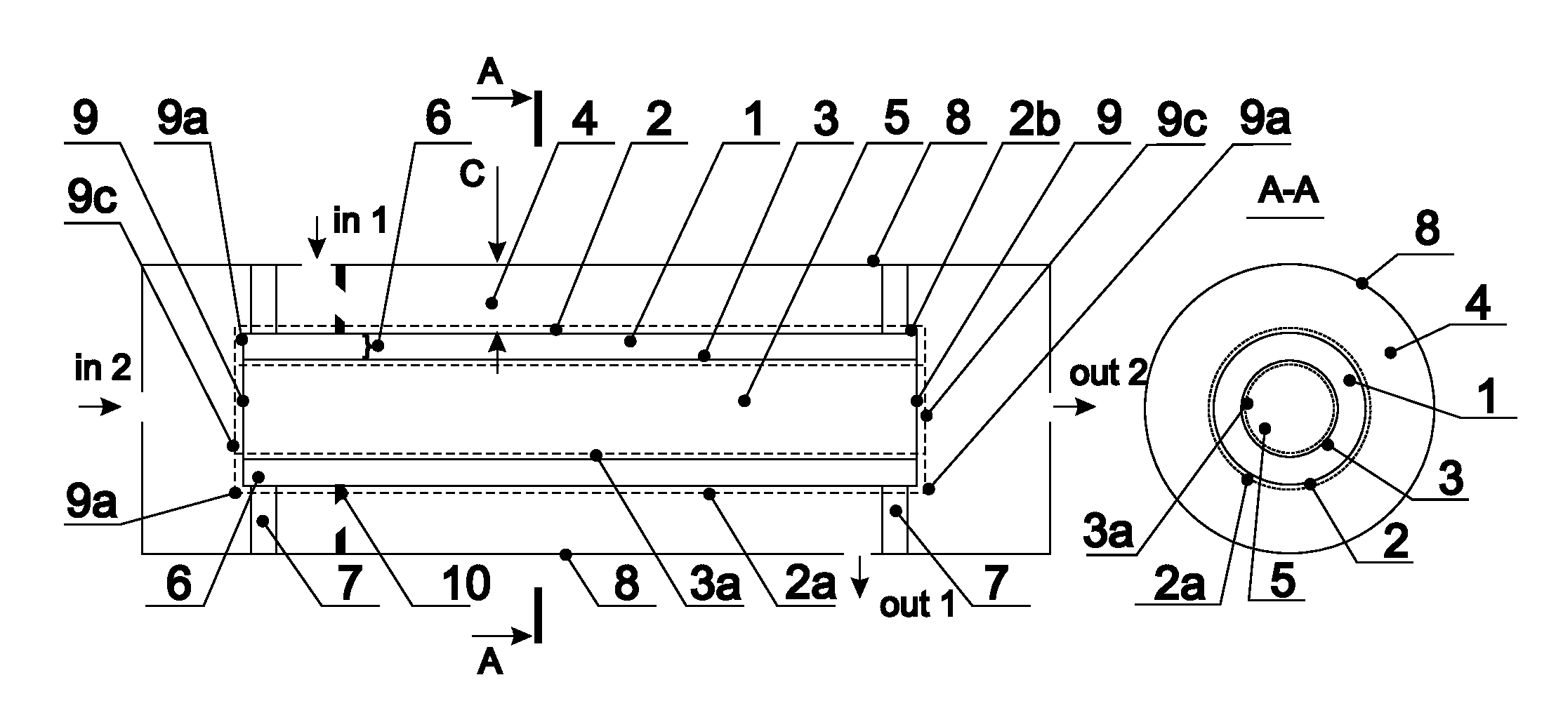
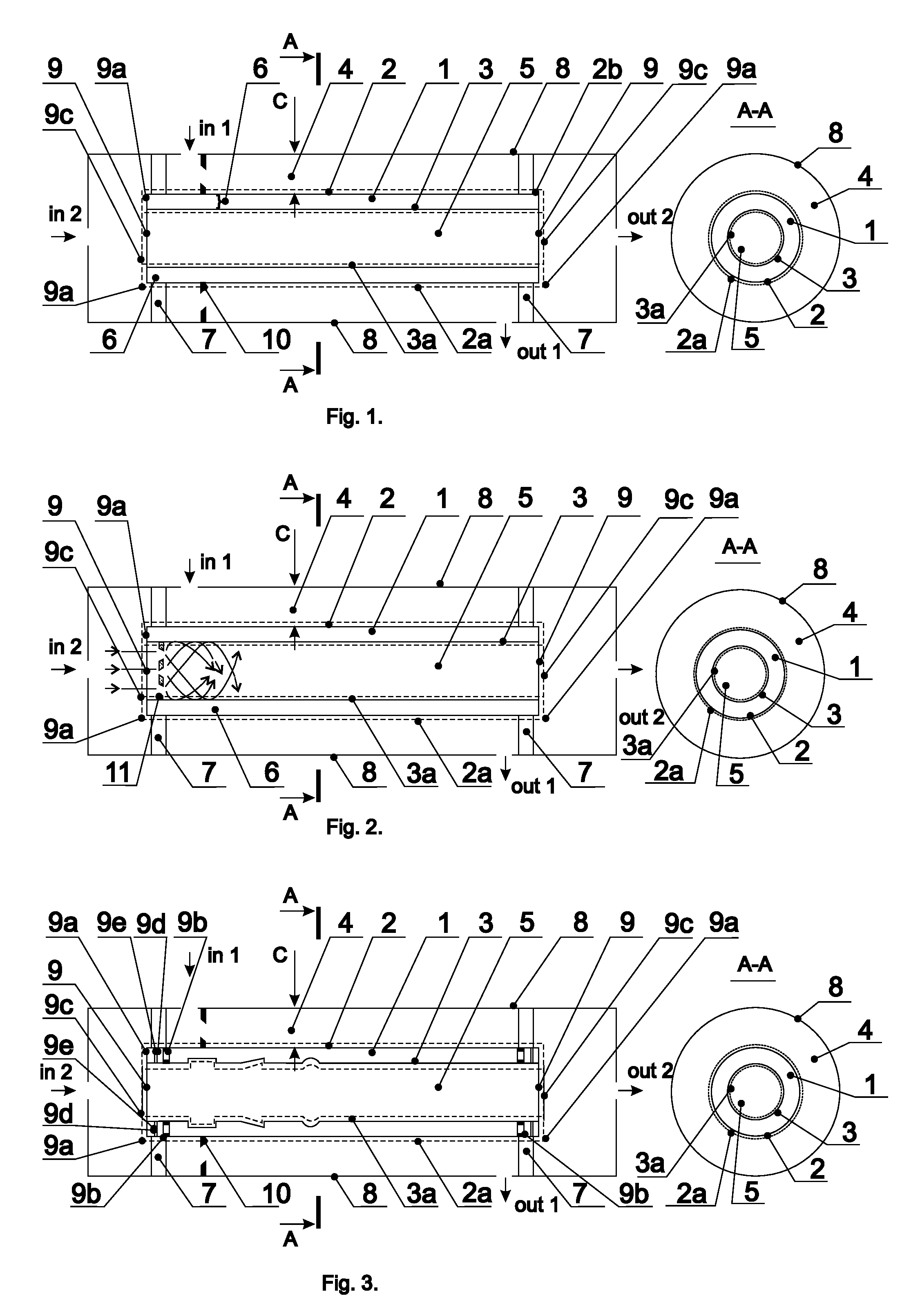
[0118]As shown in FIG. 1 and FIG. 3, in the first embodiment, the liquid to be treated may get inside space 5 of lamp 1 through inlet “in2”, and after radiation, exit reactor 21 through outlet “out2”. The gas mixture (ambient air or oxygen) for generation of oxidizing agents (ozone, singlet oxygen, hydroxyl radical, and others) enters through inlet “in1”. The oxidizing agents-containing mixture exits housing of reactor 8 through outlet “out1”.

Example

[0119]As shown in FIG. 2, in the second embodiment, the liquid to be treated may get inside housing of reactor 8 through inlet “in1”, and after radiation, exit through outlet “out1”. The gas mixture (ambient air or oxygen) for generation of oxidizing agents (ozone, singlet oxygen, hydroxyl radical, and others) generation enters housing of reactor 8 through inlet “in2”. After UV exposure, the oxidizing agents-containing mixture exits the apparatus through outlet “out2”.
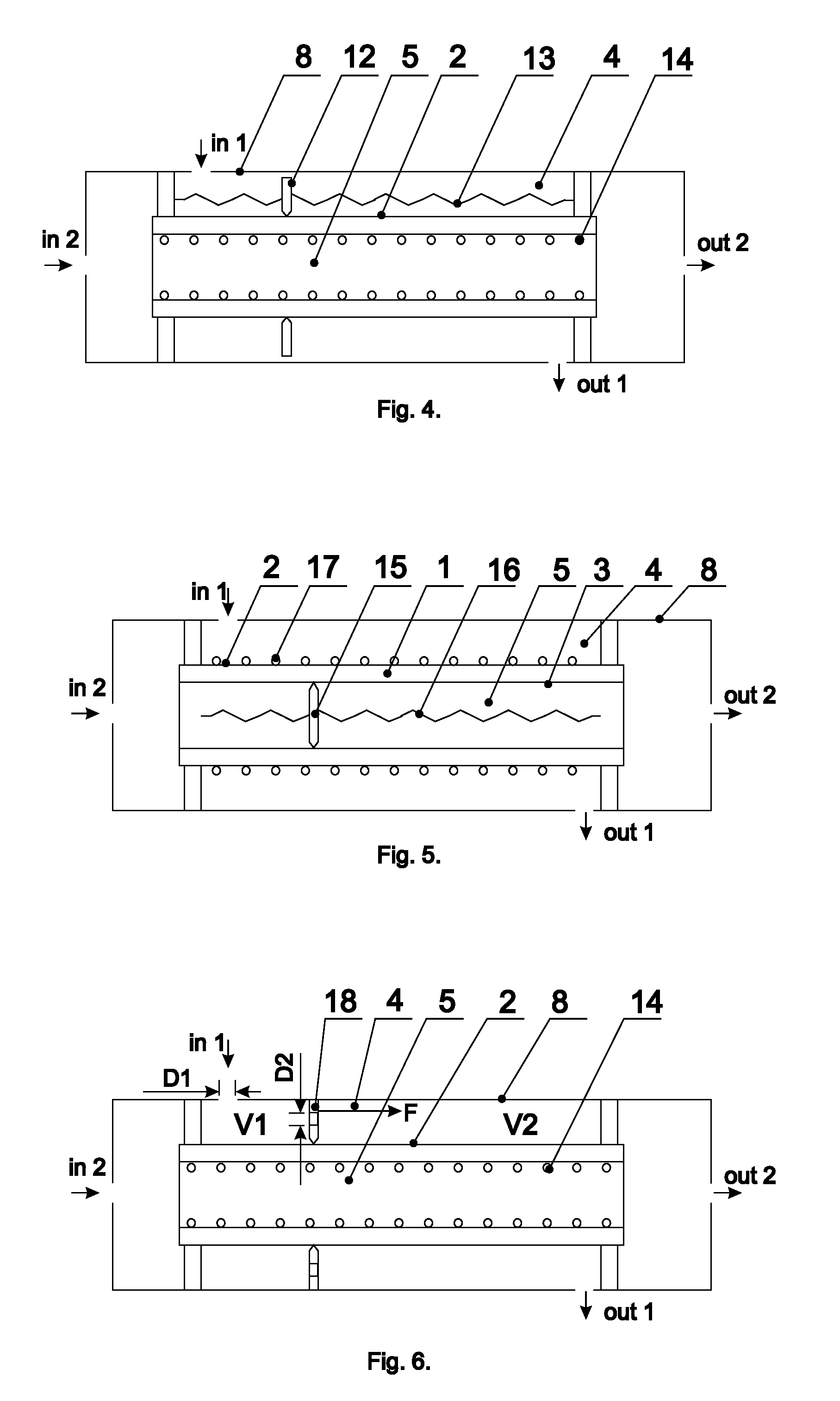
[0120]System for Cleaning the Emitting Active Surfaces of the Lamp
[0121]The lamp cleaning system comprises a set of activities aimed at removing contaminants from the emitting surface of the lamp (a sleeve adjoining the liquid being emitted. The implementation of the cleaning system may employ chemical, abrasive, or mechanical approaches.
[0122]Under the chemical approach repeated with a certain periodicity, a chemical (or a mixture of chemicals) dissolvable in the liquid and capable of removing contaminants from the emitting sleeves is added to the liquid adjoining the emitting sleeve. In this case, the liquid is declared “technical liquid” and it is supplied through different pipes. The cleaning cycle is followed by a rinsing cycle (removing the residue of the non-potable cleaning liquid from the surface of the emitting sleeve). Then, the working cycle is resumed. The excimer lamp is not turned off during the periodic cleaning, as it is a continuously operating apparatus. The technical cleaning liquid may be recycled and reused after removing the contaminants from it.
[0123]Under the abrasive approach repeated with a certain periodicity, an abrasive mixture consisting of insoluble particles forming a colloid (emulsion) and removing contaminants from the emitting sleeve is added to the liquid adjoining the emitting sleeve of reactor 1. Then the liquid is declared “technical”, and it is supplied through different pipes. The abrasive cleaning cycle is followed by a rinsing cycle (removing the residue of the technical cleaning liquid from the surface of the emitting sleeve of lamp 1. Then, the working cycle is resumed.
[0124]Positive and negative surges of pressure of the liquid being treated as well as the use of ultrasound improve the efficiency of cleaning, as the particles suspended in the liquid oscillate around the surface of an active sleeve of lamp 1.
[0125]The waste technical cleaning liquid (the liquid with insoluble particles or emulsion) may be recycled and reused after removing the contaminants from it.
[0126]Under the mechanical approach, removing contaminants from the lamp 1 emitting sleeve adjoining the liquid being treated is performed by a mechanical movement of a wiper touching the sleeve of lamp 1 and removing contaminants. The sleeve wiping takes place while the reactor with excimer lamp 1 is online and operating; there is no need to shut down or bypass the reactor.
[0127]Examples of Implementation of the Mechanical Wiping System
[0128]Example of the Mechanical Wiping System Implementation 1 (FIG. 4)
[0129]The liquid to be treated enters the reactor housing 8 through input “in1” and, after being subjected to radiation, exits through output “out1”. A screw pair system 13 resides in space 4 limited by the external wall of reactor housing 8 and the outer active reactor's sleeve 2. A driver of the screw pair system 13 (not shown in FIG. 4), resides outside space 4. The wiper 12 moves forward parallel to the axis of sleeve 2 by using rotated screw pair system 13. As wiper 1 is in contact with surface of outer sleeve 2 surface, it mechanically removes contaminants from the sleeve. The necessity of a cleaning is determined either by the performance deterioration of the reactor, or by the predetermined service schedule.
[0130]Example of the Mechanical Wiping System Implementation 2 (FIG. 5)
[0131]The liquid to be treated enters the reactor housing 8 through input “in2” and, after being subjected to radiation, exits through output “out2”. A screw pair system 16 resides in space 5 limited by inner active sleeve 3. The driver of the screw pair system (not shown in FIG. 5) resides outside space 5. Wiper 1 moves forward parallel to the axis of sleeve 3 by using of rotated screw pair system 16. As wiper 1 is in contact with lamp's sleeve 3 surface, it mechanically removes contaminants from the sleeve. The necessity of a cleaning is determined either by the performance deterioration of the reactor, or by the predetermined service schedule.
[0132]Example of the Mechanical Wiping System Implementation 3 (FIG. 6)
[0133]The liquid to be treated enters housing of reactor 8 through input “in1” and, after being subjected to radiation, exits through output “out1”. Wiper 18 is in mechanical contact with inner surface of reactor housing 8 and outer sleeve 2 of reactor 1. The surface of wiper 18 has holes of diameter D2*i and D2* 1. (*D2 is the sum of the diameters of all openings in wiper 18). D1 is the diameter of inlet “in1”. As the liquid enters housing of reactor 8 through the inlet “in1”, the pressure in area V1 becomes greater than the pressure in area V2, because of the difference of the diameters D2 and D1. The difference of the two pressures creates force F that moves wiper 18 toward exit “out1”. To make wiper 18 to move back, the input “in1” and the output “out1” are switched and the liquid to be treated flow is reversed. Hence, wiper 18 moves in the opposite direction. As wiper 18 is in contact with lamp outer sleeve 2 surface, it mechanically removes contaminants from the sleeve. Force F is great enough to overcome friction on the sleeve 2 surface. Pressure drop across the cleaning wiper 18 must be great enough to overcome the friction. The necessity of a cleaning of emitting sleeve 2 is determined either by the performance deterioration of the reactor, or by the predetermined service schedule.
[0134]The Schemes of the Media Flow
[0135]The flow schematic of the irradiated media depicts the passage of the gas and liquid to be treated as well as that of auxiliary media through excimer lamp 1, mixing and apportioning them for achieving the best result of the disinfection and/or treatment of the contaminated liquid.
[0136]The excimer UV lamp performs two physical actions affecting the liquid (disinfection and oxidation of contaminants) and changing its properties (changing redox potential of the liquid), namely, by contaminants photolysis under exposure of the contaminated liquid to the radiation (in the UV range) and by injection strong oxidizing agents (ozone, singlet oxygen, hydroxyl radical, and other) generated in a gas mixture into the liquid being treated before or after its UV irradiation in reactor 21.
[0137]The examples of schemes of the media flow in FIG. 7 through FIG. 13 and FIG. 15 through FIG. 18 are done for the second embodiment, where air enters reactor 21 through inlet “in1” and the liquid to be treated enters reactor 21 through inlet “in2”.
[0138]In FIG. 7 (Scheme 1), the air flows through gas line 20, passes air filter 19 and enters into inlet “in1” of reactor 21. This air flow is used in a pure form for production of a gas mixture or contains certain additives that increase the production of oxidizing agents after the UV radiation and corona-discharge. The air is partly is added into dosing injector 25 through gas line 26 for the saturation of the liquid to be treated with air containing additives. After a simultaneous treatment by UV radiation and corona-discharge of the air in space around outer sleeve 2 of lamp 1, the gas mixture 28 containing generated oxidizing agents flows into chamber 22. The mixing of the liquid treated with UV emitted by lamp 1, and a gas mixture containing oxidizing agents takes place in chamber 22. Then the liquid passes degasifier 29 and flows to filter 23, and then enters the next stage of treatment 24, if any. The cavitation generated by ultrasonic generator 31 may be used in dosing injector 25 and in chamber 22 for a better dissolution of the gas. This action will also generate an oxidant. The switches, power supplies, driving force, flow, valves, flow meters, etc. are not shown in the Scheme 1, FIG. 7.
[0139]Scheme 2 (FIG. 8) differs from Scheme 1 (FIG. 7) in that a gas mixture, which is fed into injector 25, has an elevated level of oxygen (produced by an oxygen generator or supplied from oxygen container 30) in order to increase the saturation of the liquid to be treated with oxygen and raise its UV exposure. The switches, power supplies, driving force, flow, valves, flow meters, etc. are not shown in the Scheme 2, FIG. 8.
[0140]Scheme 3 (FIG. 9) differs from the previous ones in that a gas mix 28 containing oxidizing agents from reactor 21 is injected into the liquid to be treated prior its expose to a UV radiation, since mixing chamber 22 is located before reactor 21 with excimer lamp 1. In this case, a gas mixture 26 may flow to injector 25 as it does in Scheme 1 (FIG. 7) or used a source of oxygen as it does in Scheme 2 (FIG. 8). The switches, power supplies, driving force, flow, valves, flow meters, etc. are not shown in the Scheme 3, FIG. 9.
[0141]Scheme 4 (FIG. 10) differs in that, in order to improve the solubility and the quality of the subsequent UV radiation treatment of the liquid to be treated, a gas mix containing oxidizing agents 28 is supplied from reactor 21 to injector 25, where it is mixed with an oxygen-containing liquid-gas mixture. Here, the gas for creation of oxygen-containing liquid-gas mixture is fed to the input of injector 25 as it does in Scheme 1 (from gas line 26) or Scheme 2 (from source of oxygen 30). The additional mixing chamber 22 may or may not be present, based on the properties of the liquid being treated. The switches, power supplies, driving force, flow, valves, flow meters, etc. are not shown in the Scheme 4, FIG. 10.
[0142]Reduction of Energy Consumption
[0143]For purposes of this invention, the energy consumption is total consumption of electrical power required for the operation of reactor 21 with excimer lamp 1, while maintaining a constant level of exposure on the liquid being treated to UV disinfection and oxidation by gas mixture. The goal of reduction of energy consumption is a reduction of the load on the electricity network, resulting in lower operating costs and increased environmental protection.
[0144]Reduction of energy consumption is achieved in two ways.
[0145]1. The utilization of a control system for adjusting of the power demand of the lamp
[0146]Gas analyzer 37 (FIG. 11) that measures the concentration of the oxidizing agents is installed in a feed line of the gas mixture 28 containing oxidizing agents in front of injector 25. The amount of oxidizing agents in the flow of gaseous medium is a function of the reactor 21 with excimer lamp 1 work in production of oxidizing agents and UV irradiation of the liquid being treated. The structure of the material of active sleeves 2 and 3 is changing with prolonged use of excimer lamp 1; it brings into existence “color centers” and other negative trends. As a result, the efficiency of excimer lamp 1, and, consequently, the entire treatment system can be reduced. Gas analyzer 37 monitors that reduction and increases the power supply to reactor 21 from power source 35 with the control feedback loop 36, which looks at loss of oxidants and increases power to generate more oxidants. (The maximum electrical current of high frequency power source 35 is less than 1 ampere).
[0147]The known treatment systems with an excimer lamp do not have such a control feedback loop system with a gas analyzer. Hence, they need to supply the maximum power to the lamp, which results in a premature wear of the lamp, a redundant capacity of power source, and the increased power consumption of the entire treatment system.
[0148]2. The utilization of air dryer 32 and air humidity meter 33 (FIG. 11)
[0149]Ambient air contains moisture, which reacts with oxidizing agents (ozone, singlet oxygen, hydroxyl radical, and others). This leads to a reduction of the oxidizing agents yield per kWh. If the humidity of the gas mixture 20 supplied to reactor 21 with excimer lamp 1 increase, the amount of oxidants produced is greatly reduced due to UV absorption by water vapor contained in gas mixture 20.
[0150]To avoid a reduction of the oxidants production, and hence, the deteriorating performance of reactor 21, the oxygen containing gas mixture 20 is dehumidified (the water vapor is removed from the gas mixture). The degree of the influent gas humidity is controlled by installed in oxygen containing feed line 20 air humidity meter (sensor of water vapor content in the gas) 33, which can either generate a signal to replace the desiccant cartridge in air drier 32 (for continuous drainage in the areas with high humidity) using alarm unit 38 via connection 34, or directly control the efficiency of the humidification process and turning air dryer 32 on and off in the areas with large fluctuations in moisture content (such as seasonal variations). Such measures provide reduction of energy consumption and operating costs for the replacement of consumable parts (desiccant cartridges) of air dryer 32. The control system operated on a feedback loop connecting vapor analyzer 33 with air dryer 32 is not shown in FIG. 11.
[0151]Optimization of Oxidant Production
[0152]In order to optimize the generation of oxidants and prevent their decomposition at electrode 17 surface (See FIG. 5, the second embodiment), which is not a liquid being treated, there should be no increase above the critical temperature on the surface of the material of the sleeves of lamp 1 and inside reactor 21. To cool the surface of active sleeve 2, on which electrode 17, which is not a liquid, is located, there is used an oxygen-containing mixture 20 supplied through “in1”. The flow rate of the oxygen-containing mixture 20 is controlled based on the readings of temperature sensor 39 (FIG. 12) mounted on the active surface of sleeve 2.
[0153]Sensor 9 readings are received and processed by analytical unit 37, which, when the temperature exceeds a critical value, increases the amount of gas entering the gas line 18. In this case, analytical unit 37 also discharges excess heat from the space inside the reactor 19 and from the surface of the sleeve 2 and the working electrode 12, through a valve 35.
[0154]Layout of the Excimer Lamps
[0155]To increase the output of the treatment system, several reactors 21 with excimer lamp 1 can be installed in parallel (FIG. 13).
[0156]Another option of increasing the output of the treatment system is an installation of several units of excimer lamp 1 in a single reactor housing 21 (FIG. 14). Then, the axial lines of three or more lamps 1 in a single reactor coincide with the geometric centers of the polygons. This type of the lamps 1 installation is used when the liquid being treated flows through space 4 (the first embodiment). The flow of liquid to be treated into reactor 21 through inlet “in2” can be perpendicular to lamps 1 (FIG. 14, Cross Section F) or parallel to lamps 1.
[0157]To increase the depth of disinfection and/or purification of the liquid to be treated, several reactors 21 can be installed in series (FIG. 15).
[0158]The schemes of liquid flow based on the second embodiment (inlet “in1” is a gas line; inlet “in2’ is a liquid line).
[0159]There are three modes of liquid flow during the operations of the rector—normal mode, cleaning up the lamp, and flushing mode.
[0160]In normal mode (FIG. 16) the liquid being treated passes through the lamp 1. In this mode, valves 42 and 43 are open; valves 44, 45, 46, and 47 are closed.
[0161]Under the mode of cleaning up the lamp (FIG. 17), the cleaning liquid is pumped from tank 48 under pressure through tee fitting 49 into the lamp 1 for cleaning the working sleeve. In this mode, valves 42, 43, and 46 are closed; valves 44, 45, and 47 are open.
[0162]Here the liquid moves through a closed loop, in which filter 50 for cleaning and regeneration of this liquid is provided.
[0163]In the flushing mode (FIG. 18), the cleaning liquid left in is removed from the system. In this mode, valves 42, 47, and 46 are open; valves 44, 45 and 43 are closed.
[0164]Lamp 1 returns to the normal mode of operations after completion of the flushing mode.
[0165]Diagrams of Electrical Connections
[0166]If the electrode, which is not a liquid, is adjacent to the surface of the inner sleeve 3 of excimer lamp 1, then this electrode 14 is powered by a high-voltage source 35. Then, the liquid located in space 4 acts as the ground electrode (FIG. 19).
[0167]If the electrode, which is not a liquid, is adjacent to the surface of the outer sleeve 2 of excimer lamp 1, then this electrode 17 is powered by a high-voltage source 35. Then, the liquid located in space 5 acts as the ground electrode (FIG. 20).
[0168]If both electrodes are liquids, then, provided that the necessary electrical junctions are available, the function of the high-voltage electrode can play any of two liquid flows, as one in contact with the outer sleeve 2 (the liquid in space 4) (FIG. 21, Cross Section A) or the second one, which is in contact with the inner sleeve 3 (the liquid in space 5) (FIG. 21, Cross Section B) because the liquid is in contact with both outer sleeve 2 and inner sleeve 3.
[0169]Although the present invention has been described with reference to specific exemplary embodiments, it will be evident that the various modification and changes can be made to these embodiments without departing from the broader spirit of the invention as set forth in the claims. Accordingly, the specification and drawings are to be regarded in an illustrative sense rather than in a restrictive sense.

PUM

no PUM

Description & Claims & Application Information

We can also present the details of the Description, Claims and Application information to help users get a comprehensive understanding of the technical details of the patent, such as background art, summary of invention, brief description of drawings, description of embodiments, and other original content. On the other hand, users can also determine the specific scope of protection of the technology through the list of claims; as well as understand the changes in the life cycle of the technology with the presentation of the patent timeline. Login to view more.

Similar technology patents

BDD composite electrode material and preparation method for same, BDD composite electrode

ActiveCN110643957Alow energy consumptionGood electrical and electrochemical properties
Owner:河南省功能金刚石研究院有限公司 +1

Method for drying lithium ion battery pole pieces

InactiveCN104028439Ashort drying timelow energy consumption
Owner:赖昭文

Flue gas desulfurization and denitrification system

Owner:NANJING BAIYUN CHEM ENVIRONMENTAL MONITORING

Classification and recommendation of technical efficacy words

Why Eureka
Try Eureka