Fuel tank temperature and pressure management via selective extraction of liquid fuel and fuel vapor

a technology of liquid fuel and fuel vapor, which is applied in the direction of pressure vessels, containers discharging from pressure vessels, non-pressured vessels, etc., can solve the problems of fuel being more likely to produce unwanted particulate emissions in the exhaust, refilling (or refueling), and consumers being starved of fuel, so as to reduce the vapor pressure inside the fuel tank

Inactive Publication Date: 2014-07-22
GM GLOBAL TECH OPERATIONS LLC
View PDF15 Cites 18 Cited by
  • Summary
  • Abstract
  • Description
  • Claims
  • Application Information

AI Technical Summary

Benefits of technology

[0018]By way of non-limiting example, like the aforementioned prior art gaseous-phase manifold-injection LPG fuel systems, the present invention supplies fuel to a fuel consumer via a vaporizer and pressure regulator (vaporizer-regulator); however, in contrast thereto, the present invention supplies the fuel to the vaporizer-regulator, under at least some operating conditions, e.g., where the vapor pressure in the fuel tank is greater than the minimum fuel feed pressure requirement of the vaporizer-regulator, as a variable ratio of liquid fuel to fuel vapor in the fuel feed upstream of the vaporizer so as to provide additional functionality over the prior art, namely: i) management of the temperature and, hence, the vapor pressure of the fuel in the tank to reduce the likelihood of a no-fill situation and / or reduce the time required to fill the fuel tank; and / or ii) increase the proportion of fuel vapor in the fuel feed to the vaporizer-regulator under operating conditions in which it may be undesirable, difficult or impossible for the vaporizer to provide sufficient heat energy to reliably vaporize all of the liquid fuel which would otherwise enter the vaporizer (e.g., in the event of occurrence of a cold episode, or as an assist to the vaporizer if the fuel heater within the vaporizer is functionally inadequate to meet mass flow demand of the fuel consumer).
[0019]In general, the fuel systems according to the present invention must address the following functionality requirements in addition to those of the prior art: 1) meet increased proportion of fuel vapor in the fuel feed to the vaporizer-regulator under operating conditions in which it may be undesirable, difficult or impossible for the vaporizer to provide sufficient heat energy to reliably vaporize all of the liquid fuel which would otherwise enter the vaporizer; 2) meet management of the temperature and, hence, vapor pressure of the fuel in the fuel tank in order to reduce the likelihood of a no-fill situation; 3) meet management of the temperature and, hence, vapor pressure of the fuel in the fuel tank in order to reduce the time required to re-fill (re-fuel) the fuel tank; and 4) meet minimized operation and / or duty cycle of fuel flow control unique to the present invention, wherein the objective is to reduce noise generated by fuel flow control and / or reduce electrical energy consumption and / or increase service life of the fuel flow control(s).
[0021]Fuels which are stored at, or close to the vapor pressure of the fuel may be multi-component mixtures (for example, LPG is typically a mixture of multiple components including propane, butane and other hydrocarbons). In the case of such multi-component fuel mixtures, there may be small differences between the chemical composition of the fuel vapor and of the liquid fuel in the same fuel tank. Furthermore, it may also be the case that the chemical composition of the fuel vapor in the fuel tank varies to a greater extent than the chemical composition of the liquid fuel in the fuel tank as the fuel tank is emptied. (For a discussion of the technical reasons behind these chemical composition differences, refer to SAE technical paper 981388 ‘The Effects of Fuel Composition, System Design and Operating Conditions on In-System Vaporization and Hot-Start of a Liquid-Phase LPG Injection System’ by Lutz et al). These chemical composition differences may, in turn, result in small differences in fuel energy content and stoichiometric air to fuel ratio as the fuel feed is switched from fuel which is mostly in a liquid phase to fuel which contains a larger amount of vapor phase, or vice-versa, in accordance with the present invention. However, fuel consumers which burn fuel composed of multi-component mixtures are typically tolerant, within limits, to fuel composition variation. Such systems will typically also be tolerant to the variation in chemical composition caused by switching from fuel which is mostly in a liquid phase to fuel which is mostly in a vapor phase. However, in some applications, it is possible that the rate of switching between fuel which is mostly in a liquid phase to fuel which is mostly in a vapor phase may need to be limited to prevent potential problems associated with sudden ‘step’ changes in fuel composition.
[0022]Another aspect of LPG and other fuels which are stored at vapor pressure and which typically have multiple chemical components, is that the chemical components will each have differing vapor pressures. Examples of high vapor pressure components which may be present in LPG fuels include: ethane, nitrogen and carbon dioxide; and tank manufacture or servicing may introduce air (or other contaminant gases such as nitrogen used for leak detection) into the tank, which may not have been completely purged out. The vapor pressure inside the fuel tank is the vapor pressure of the fuel mixture, however the individual chemical components may have a vapor pressure which is higher or lower than the vapor pressure of the mixture. Because high vapor pressure chemical components have an increased tendency to remain in their gaseous phase and therefore ‘compress’ rather than ‘condense’ as the pressure inside the fuel tank increases, ability to refill the tank is adversely affected. Advantageously, the present invention provides: 1) the ability to selectively remove high vapor pressure chemical components at a faster rate than can be achieved with a prior art fuel systems which typically draw only liquid fuel from the fuel tank, rendering the fuel system more tolerant to fuel composition variation vis-a-vis refilling problems; 2) ability to remove contaminant chemical components after manufacture or servicing; and 3) ability to selectively retain high vapor pressure components inside the fuel tank (i.e., similar to the retention of high vapor pressure components by a prior art liquid-feed fuel system), which may be for example desirable under low-temperature operating conditions when a high fuel tank pressure will help to reduce the need to increase the pressure by alternative means (e.g., by activating a fuel pump).

Problems solved by technology

The longer chain hydrocarbons of gasoline and diesel fuel are also more likely to produce unwanted particulate emissions in the exhaust gas.
One issue which can be encountered with prior art LPG fuel systems, as well as other pressurized fuel systems in general, concerns refilling (or refueling) when the pressure within the fuel tank is too high relative to the pressure at the nozzle of the bowser (or refilling station) to permit reasonably rapid refilling, or indeed, too high to permit any refilling (a no-fill situation).
Another issue which can be encountered in prior art LPG fuel systems, as well as other pressurized fuel systems in general, concerns delivery of vapor to the fuel consumer thereof during cold episodes (as for example a cold engine start in cold weather), wherein the ability of the vaporizer to provide complete fuel vaporization may be less than required to achieve 100% fuel vaporization at a mass flow rate demanded of the fuel consumer, whereby the consumer could become starved of fuel.

Method used


Image

  • Fuel tank temperature and pressure management via selective extraction of liquid fuel and fuel vapor
  • Fuel tank temperature and pressure management via selective extraction of liquid fuel and fuel vapor
  • Fuel tank temperature and pressure management via selective extraction of liquid fuel and fuel vapor

Examples


embodiment 300

[0089]Turning attention firstly to FIG. 8, a first exemplar embodiment 300 is depicted of the fuel tank temperature and pressure management system according to the present invention, in which control states CS1, CS2 and CS7 of Table 1 are applicable thereto.

[0090]In this LPG fuel system first embodiment 300, LPG fuel 304 in the top of the fuel tank 302 is a saturated fuel vapor (or simply, a vapor) 304V, and therebelow is disposed liquid fuel 304L, wherein the fuel may be any fuel stored at or near its vapor pressure, and need not be LPG.

[0091]The fuel tank 302 is equipped with a pressure relief valve, and may be equipped with a temperature sensor and a pressure sensor, not shown, but each component having been described in detail hereinabove; and the contents of the fuel tank may be subjected to various heats (not shown) as also described in detail hereinabove.

[0092]Contained within the fuel tank 302 are components of a prior art fuel system 306, namely a filter 308, a fuel pump 31...

first embodiment

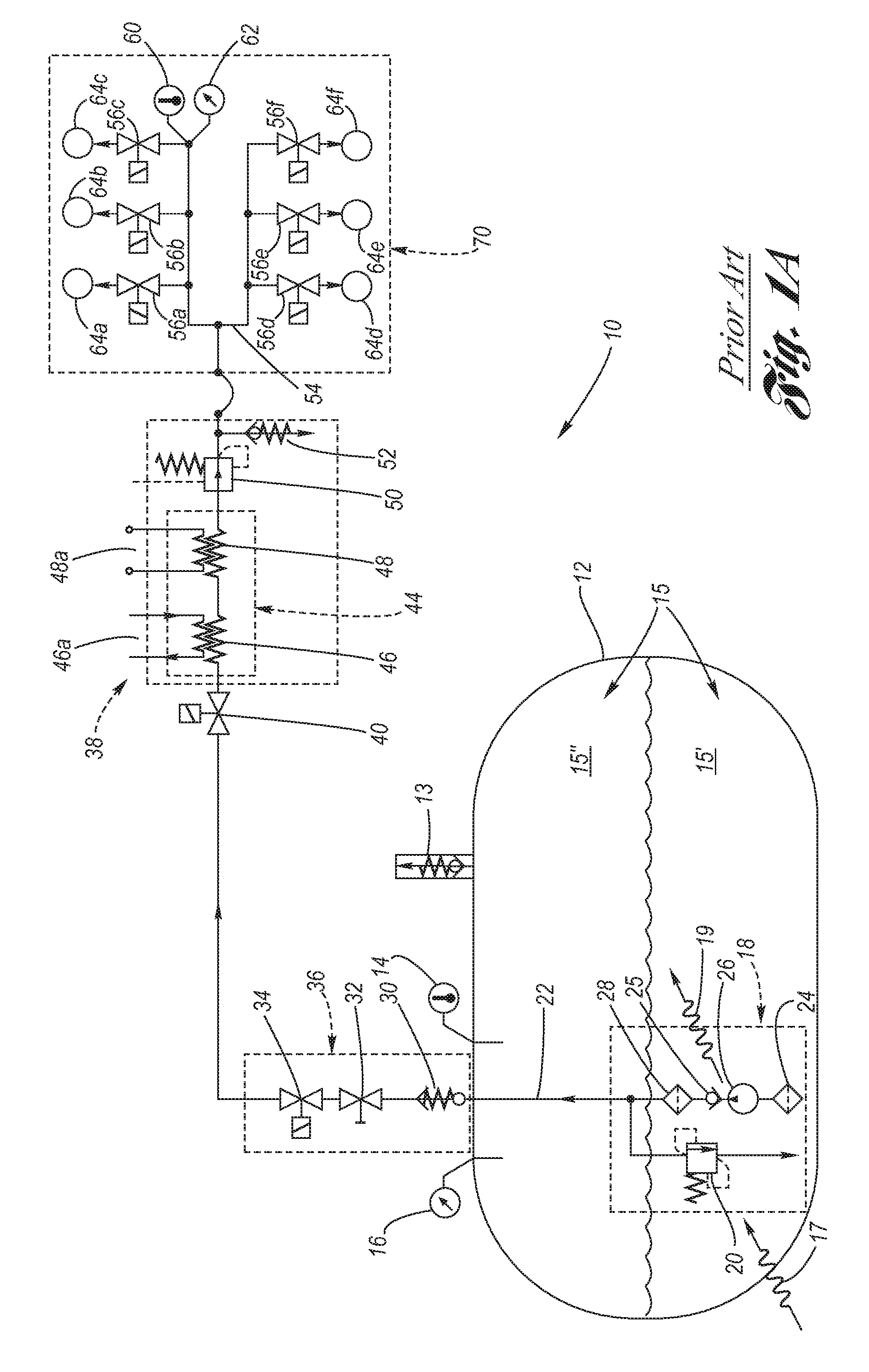
[0098]The first embodiment is preferred for its simplicity. It should be noted that in the event that check valve 334 fails closed, then the system reverts to the functionality of the prior art fuel system of FIG. 1A. If however check valve 335 fails open, then this could be problematic from the standpoint of liquid fuel delivery via FF1; to reduce the risk of this failure mode, two or more check valves 334 can be fitted in series if required.

[0099]Turning attention now to FIG. 9, a second exemplar embodiment 340 is depicted of the fuel tank temperature and pressure management system according to the present invention, which is a variant of the first embodiment 300 to now have applicability thereto of control states CS1 through CS4, inclusive, and CS7 of Table 1 (two additional control states (CS3 and CS4) relative to the first embodiment), wherein numerals identical to FIG. 8 will be used to designated identical components.

[0100]In this LPG fuel system second embodiment 340, LPG fu...

embodiment 370

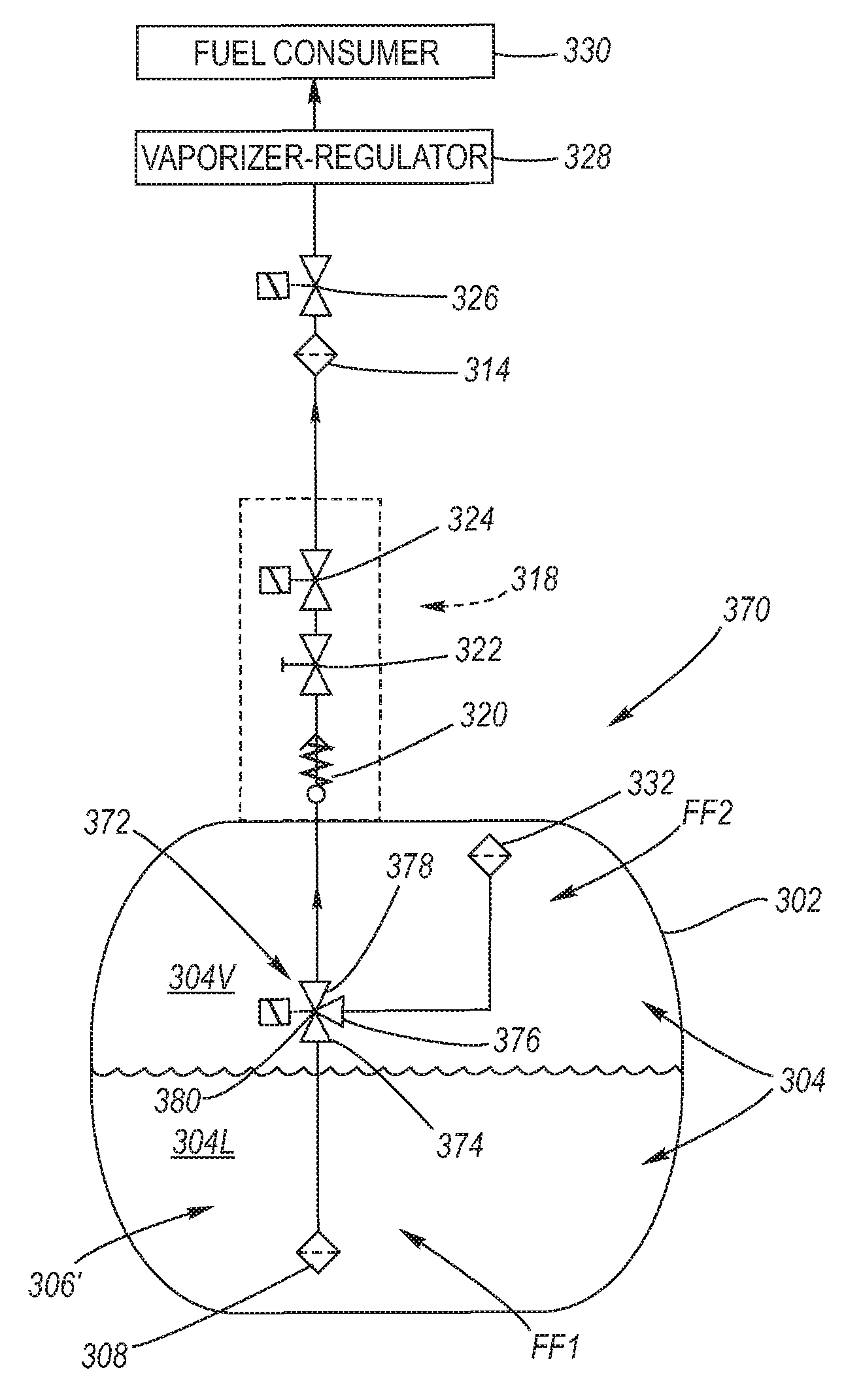
[0116]Turning attention next to FIG. 11, a fourth exemplar embodiment 370 is depicted of the fuel tank temperature and pressure management system according to the present invention, in which control states CS3 through CS9, inclusive, of Table 1 are applicable thereto, and wherein numerals identical to FIG. 8 will be used to designate identical components.

[0117]In this LPG fuel system fourth embodiment 370, LPG fuel 304 in the top of the fuel tank 302 is a saturated fuel vapor (or simply, a vapor) 304V, and therebelow is disposed liquid fuel 304L, wherein the fuel may be any fuel stored at or near its vapor pressure, and need not be LPG.

[0118]The fuel tank 302 is equipped with a pressure relief valve, and may be equipped with a temperature sensor and a pressure sensor, not shown, but each component having been described in detail hereinabove; and the contents of the fuel tank may be subjected to various heats (not shown) as also described in detail hereinabove.

[0119]Contained within ...


PUM


Abstract

A method and apparatus for managing temperature and pressure of fuel in a fuel tank stored at or near its vapor pressure. In response to fuel feed pressure, a variable ratio of liquid fuel to fuel vapor is extracted from the fuel tank in order to regulate temperature and pressure of the fuel for the purpose of keeping the pressure lower in anticipation of refilling or to assist a vaporizer of the fuel system which is incompletely vaporizing the fuel.

Description

TECHNICAL FIELD[0001]The present invention relates to the temperature and pressure management of fuel supply systems where fuel is stored in a fuel tank (or vessel) at, or close to, the vapor pressure of the fuel.BACKGROUND OF THE INVENTION[0002]Motor vehicle designers continually strive to create vehicles which have lower emissions of noxious and greenhouse gases than vehicles currently in use. One means of reducing vehicular emissions is to utilize alternative fuels. Commonly used fuels, such as gasoline and diesel fuel, are mixtures of complex hydrocarbons which may also contain unwanted chemicals, such as sulfur. One form of alternative fuel, for non-limiting example, is liquefied petroleum gas (LPG). LPG is primarily composed of propane, a three carbon hydrocarbon, and butane, a four carbon hydrocarbon. These hydrocarbons have a lower carbon to hydrogen ratio than gasoline or diesel fuel. Because the carbon to hydrogen ratio is lower, less carbon dioxide is produced in the burn...

Claims


Application Information

Patent Timeline
Patent Type & Authority Patents(United States)
IPC IPC(8): F23N1/00F02M21/06F02M37/00
CPCY10T137/86027F02D41/0027F02D19/022F02D19/023F02M21/0245F02D19/027F02M21/0221F17C9/02B60K15/035F02M21/06F02M21/0212F17C13/00Y10T137/0396F02D41/00F17C7/04Y10T137/3115Y02T10/32Y10T137/7837F17C3/00F17C13/025F17C2205/0332F17C2205/0341F17C2221/035F17C2223/0153F17C2223/033F17C2227/0135F17C2227/0178F17C2250/043F17C2250/0439F17C2250/0491F17C2250/0626F17C2250/0631F17C2250/075F17C2260/021F17C2260/026F17C2265/066F17C2270/0178Y02T10/30B60K15/077B60K15/03
Inventor CARTER, NICHOLASHURLEY, RICHARD W.ARCHER, MARK D.WOOLLEY, ALEC G.EDSELL, JON D.
Owner GM GLOBAL TECH OPERATIONS LLC
Why Eureka
Try Eureka