Nanolaminate-reinforced metal composite tank material and design for storage of flammable and combustible fluids

a technology of nanolaminate and reinforced metal, which is applied in the direction of transportation and packaging, transportation items, packaging, etc., can solve the problems of explosion, rapid spreading flames, and explosion, and both liquid and gaseous fuel can escape unimpeded from conventional fuel tanks, and achieves greater vehicle traveling distance, high energy density, and high strength-to-weight ratio

Active Publication Date: 2015-08-18
MODUMETAL LLC
View PDF5 Cites 17 Cited by
  • Summary
  • Abstract
  • Description
  • Claims
  • Application Information

AI Technical Summary

Benefits of technology

[0007]The present disclosure applies to storage of pressurized gases, especially those used as vehicle fuel where tank volume, weight, shape, and strength all contribute to the overall energy density of the gaseous fuel. By employing composite materials, and in particular composite materials including a nanolaminated alloy, higher strength-to-weight and strength-to-volume ratios can be achieved compared with conventional pressurized gas storage tanks, resulting in higher energy densities and greater vehicle traveling distance. Compressed hydrogen storage is one example of such an application.
[0008]One aspect of the present disclosure is to provide a material for the construction of storage tanks for combustible and flammable fluids which incorporates the benefits of an open cellular baffle system with the advantageous material properties of a nanolaminated alloy in order to protect against tank penetration and reduce the risk of flame spread and explosion in case of a tank penetration.
[0009]Another aspect of this disclosure is to provide a method for the production of said storage tanks which allows for control of the nanolaminate alloy composition such that, for example, highly corrosion and chemical resistant alloys can be incorporated into the design, specific structural and protective characteristics can be met, and / or specific tank geometries may be realized.
[0010]In yet another aspect, the present disclosure provides a design, employing said material, for a fuel tank which both resists penetration by ballistic impacts, prevents or lessens flame spread and explosion in the event of penetration, and prevents or lessens fuel foaming during fueling operations.

Problems solved by technology

Vehicles (automobiles, tanks, airplanes, boats, etc.) typically possess fuel tanks in which liquid fuel is free to move, or ‘slosh’, often resulting in a build up of static charge and an accompanying risk of ignition and subsequent explosion.
Additionally, both liquid and gaseous fuel can escape unimpeded from conventional fuel tanks in the event of an accidental or intentional penetration of the tank.
The risk of explosion and rapidly spreading flames resulting from either of these factors pose serious threats to the vehicle, vehicle occupants, and people or structures in the area.
The plastic foam baffles tend to chemically degrade over time, and the debris generated can plug fuel filter systems.
The foam baffles also complicate fueling procedures as the fuel tends to foam on contact with the baffle system, thus limiting fueling rates.
Debris may also build up and block the foam, thereby reducing fuel tank volume.
Furthermore, while plastic foam baffle systems help mitigate spillage in the case of a tank penetration, these foams provide little to no structural reinforcement and therefore do not inhibit the penetration itself.
These fibers further serve to absorb liquid fuels, thereby reducing their mobility and slowing their combustion.
While inhibiting flame spread and explosion, the materials of U.S. Pat. No. 4,844,974 provide minimal structural reinforcement, and therefore do not enhance resistance of the storage container to puncture.

Method used


Image

  • Nanolaminate-reinforced metal composite tank material and design for storage of flammable and combustible fluids
  • Nanolaminate-reinforced metal composite tank material and design for storage of flammable and combustible fluids
  • Nanolaminate-reinforced metal composite tank material and design for storage of flammable and combustible fluids

Examples


example 1

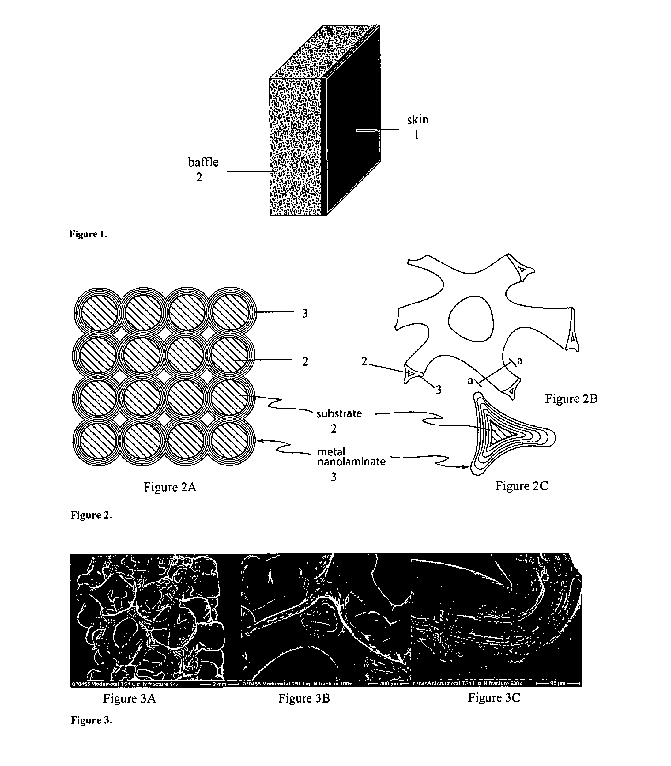
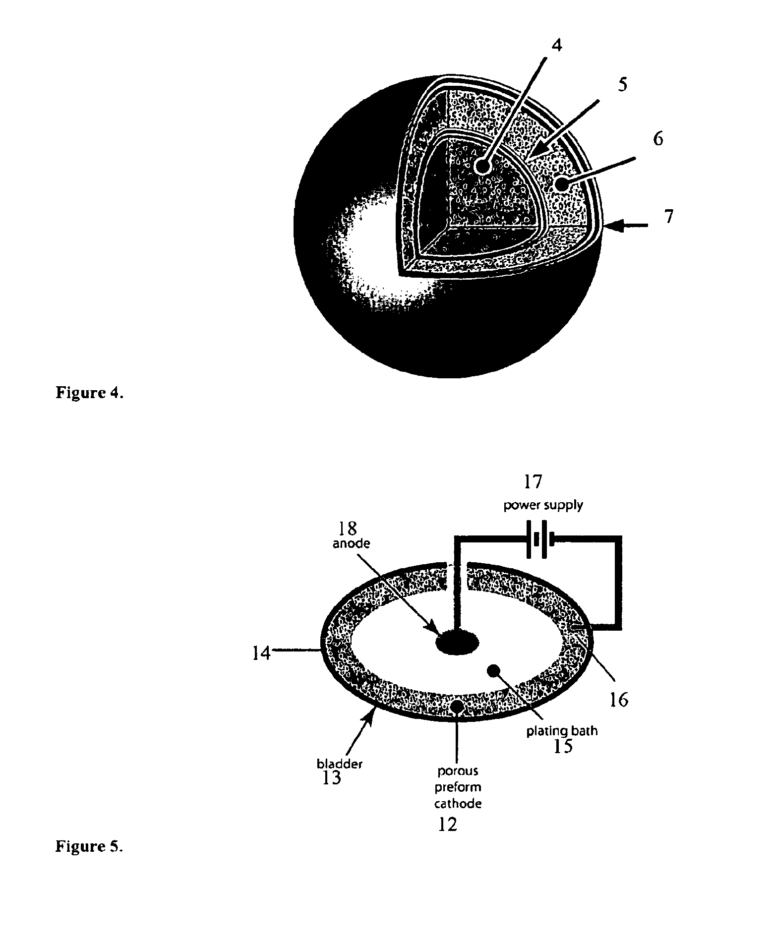
[0074]A fuel tank for a vehicle can be formed to have an interior portion made from a preform of reticulated vitreous carbon, a fuel shell made of a nanolaminate coating including Ni and Fe, an exterior foam or porous layer formed of a conductive fabric, and an exterior shell including a Ni / Fe nanolaminate coating (which can either be identical to the fuel shell layer or have a different composition and / or structure than the fuel shell layer). Both the fuel shell and exterior shell nanolaminate coatings are formed by means of electrodeposition.

[0075]To form the fuel tank, a bath including 0.2M Ni(NH2SO3)2●4H2O, 0.2M FeCl2●4H2O, 0.40M H3BO3, 1.5 g / L sodium saccharin, 0.2 g / L sodium dodecyl sulfate, 1.0 g / L ascorbic acid, and enough sulfamic acid or nickel carbonate to attain a pH level of 3.00±0.01 is prepared. Anodes formed of titanium baskets including nickel S-rounds are obtained. The baskets are selected such that a nominal basket area is equal to or greater than a nominal workpi...

example 2

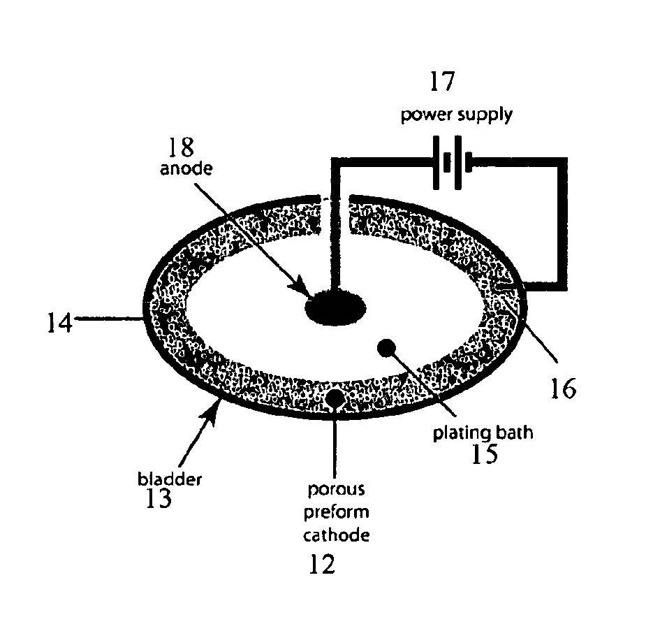
[0083]A small rectangular composite fuel tank including a 20 PPI (pores per inch) reticulated vitreous carbon foam preform and an electrodeposited compositionally modulated NiFe alloy was formed in a laboratory using the following procedure. A bath was prepared using 0.2M Ni(H2NSO3)2●4H2O, 0.04 M FeCl2●4H2O, 0.40M H3BO3, 1.5 g / L sodium saccharin, 0.2 g / L sodium dodecyl sulfate, 1.0 g / L ascorbic acid, and sulfamic acid to attain a pH of 3.00±0.01. A 10″ by 10″ by 1″ piece of 20 PPI reticulated vitreous carbon foam preform was rigidly mounted in an insulating frame which suspended the preform in the frame's center by a finite number of small conducting elements, or contacts. The contacts were contained and insulated within the frame such that they did not come into contact with the electroplating bath once immersed, and terminated at a single bus located at the top edge of the insulating frame. This bus was in turn connected to two 10 gauge hooks which allowed the entire assembly to h...

example 3

[0088]A small rectangular composite fuel tank including a 20 PPI (pores per inch) reticulated vitreous carbon foam preform and an electrodeposited nickel reinforcement was formed in a laboratory using the following procedure.

[0089]A commercial nickel sulfamate plating bath was purchased from Technic, Inc. A 10″ by 10″ by 1″ piece of 20 PPI reticulated vitreous carbon foam preform was rigidly mounted in an insulating frame which suspended the preform in the frame's center by a finite number of small conducting elements, or contacts. The contacts were contained and insulated within the frame such that they did not come into contact with the electroplating bath once immersed, and terminated at a single bus located at the top edge of the insulating frame. This bus was in turn connected to two 10 gauge hooks which allowed the entire assembly to hang from a bus bar mounted across the top of a plating tank. The frame was designed to provide electrical contact to the preform while not distu...


PUM

PropertyMeasurementUnit
modulation wavelengthaaaaaaaaaa

Abstract

An improved fuel tank and method of forming a fuel tank utilize reinforced porous metal composite materials. In one embodiment, the composite material includes a fully dense, fluid-impermeable skin combined with a porous metal baffle. The skin and baffle may be formed as a single monolithic system via electrodeposition of a nanolaminate material into at least a portion of open, accessible void space within a porous preform (e.g., a metal foam preform) and on the exterior surface of the preform to form the fluid-impermeable skin.

Description

[0001]This application is a 371 of International Application No. PCT / US2008 / 069325 filed Jul. 7, 2008, which published as WO 2009 / 045593, and which claims priority to Provisional Application No. 60 / 948,303 filed Jul. 6, 2007. The entire contents of the above-identified applications are hereby incorporated by reference.FIELD OF THE DISCLOSURE[0002]This disclosure relates to an improved material, process, and design for constructing storage tanks for flammable and combustible fluids. Storage tanks produced using the disclosed methods and materials will a) reduce the risks of flame spread and explosion in the event of both low- and high-strain-rate (ballistic) impacts, b) allow for the production of arbitrary, conformable tank geometries, and c) provide enhanced strength-to-weight ratios over existing storage tanks for combustible and flammable fluid storage. Additional advantages afforded by the claimed material include resistance to chemical attack and enhanced dissipation of both he...

Claims


Application Information

Patent Timeline
Patent Type & Authority Patents(United States)
IPC IPC(8): B60K15/03C25D5/10B22F7/00B60K15/077C25D7/00F42D5/04C25D15/02
CPCB60K15/03B22F7/004C25D5/10C25D7/00C25D15/02F42D5/04B22F3/11B22F2998/10B60K2015/0344B60K2015/0777C25D5/617
Inventor WHITAKER, JOHN D.LOMASNEY, CHRISTINA A.
Owner MODUMETAL LLC
Why Eureka
Try Eureka