Method of forming a tissue scaffold

a tissue and scaffold technology, applied in the field of tissue scaffolding, can solve the problems of large risk of disease transfer, potential mechanical failure, patient immuno-rejection of implants,

Active Publication Date: 2016-10-11
UNIVERSITY OF ULSTER
View PDF16 Cites 1 Cited by
  • Summary
  • Abstract
  • Description
  • Claims
  • Application Information

AI Technical Summary

Benefits of technology

[0021]In some embodiments of the invention according to any of its aspects, the method may further comprise a step of incorporating a stent into the tissue scaffold. The stent could be mounted onto the template before the deposition process begins permitting the stent to be incorporated into the scaffold structure during the polymer fibre deposition process. The stent could also be attached by physical, chemical, mechanical or any other means, inside or outside the scaffold structure in order to aid this function or to aid a mechanical or additional structural function after the scaffold has been made or at any stage during the deposition process. The stent could be applied to the scaffold after the deposition process has been completed. In embodiments where the tissue scaffold is a heart valve scaffold, the stent can aid in the deployment of the heart valve scaffold via a minimally invasive transcather surgical procedure.

Problems solved by technology

However, notwithstanding the surgical risks, there are still many problems associated with these types of HVRs.
In the case of mechanical valves, they have the potential to undergo actual mechanical failure as they have a limited lifespan (8-10 years) and are prone to calcification / clotting.
Although bio-prosthetic valves are made from a de-cellularised biological source, thus addressing some of the issues associated with mechanical valves, there is still a large risk of disease transfer and, more importantly, immuno-rejection of the implant by the patient.
As a result, new heart tissue formation and regeneration, if any, is therefore limited.
Although attempts have been made to engineer HVRs by electrospinning fibers to form artificial scaffolds, they have failed to generate scaffolds which adequately mimic the biological and mechanical properties of natural donor scaffolds from bio-prosthetic valves.

Method used


Image

  • Method of forming a tissue scaffold
  • Method of forming a tissue scaffold
  • Method of forming a tissue scaffold

Examples


examples

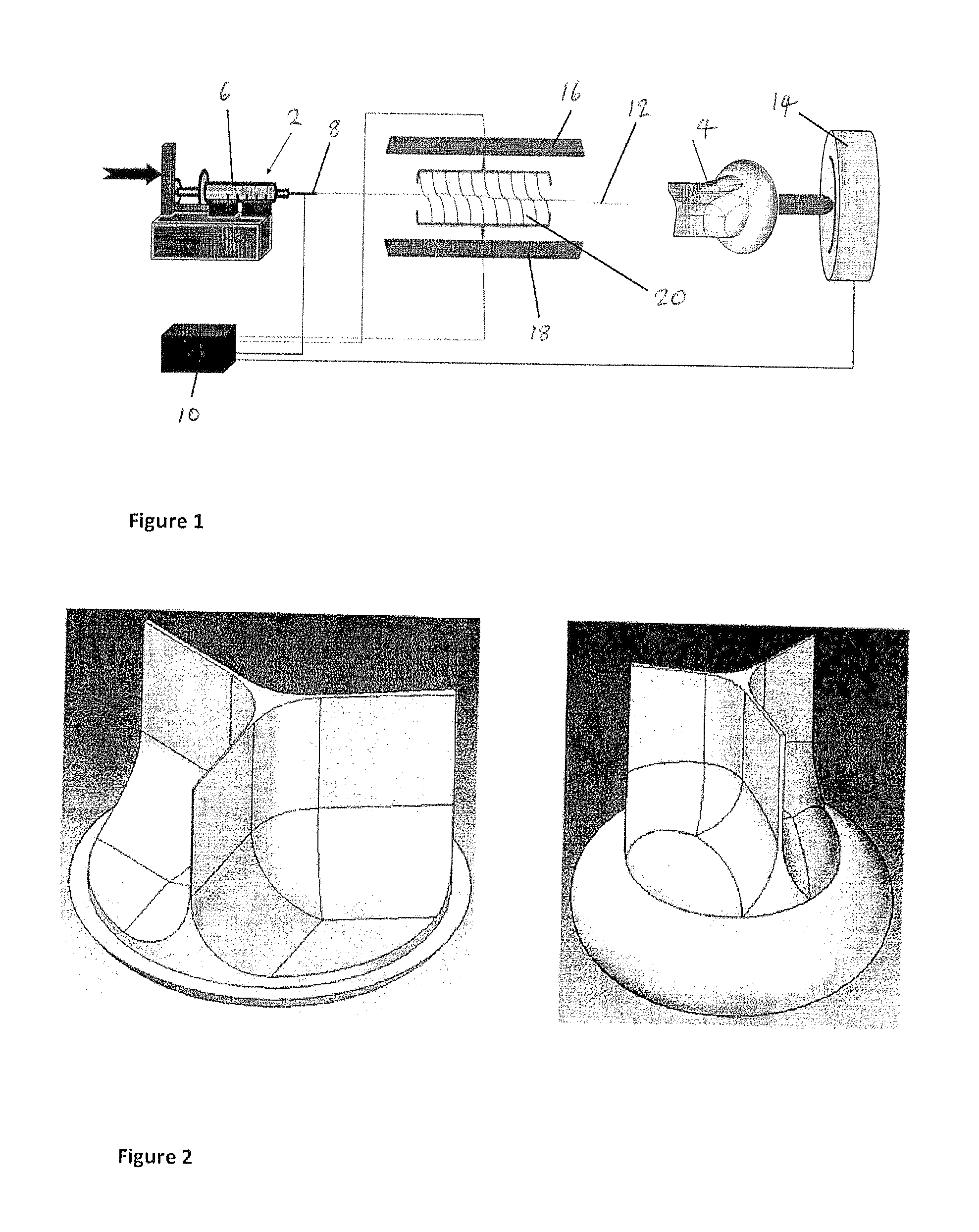
Heart Valve Scaffold Formation

[0042]In one example, it was been found that the following conditions were particularly suitable for the formation of a tissue scaffold that is in the form of a heart valve scaffold of a given dimension i.e. thickness.

[0043]The polymer used was a PCL (polycaprolactone) polymer obtained from PURAC®. The polymer was PURASORB® PLC 7015 70 / 30 L-lactide / caprolactone copolymer, IV midpoint 1.5 dl / g. The composition was as follows;[0044]Comonomer ratio, L-lactide 68 mol %[0045]Comonomer ration, Caprolactone 32 mol %[0046]water content max 0.5%[0047]Tin content max 100 ppm[0048]Residual solvent max 0.1%[0049]Residual monomer max 0.5%

It is understood that the quantity of heavy metals present would comply with USP test methods for the presence of heavy metals if tested.

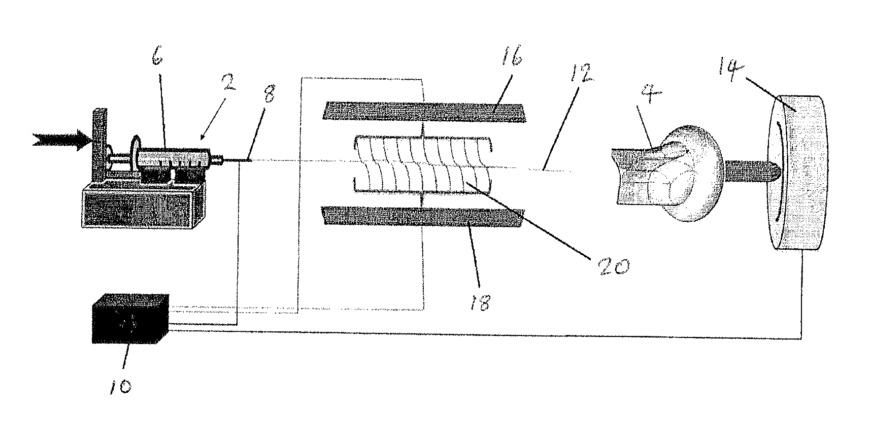
[0050]The PCL polymer was present at 10% weight by volume in a solvent comprising 90% chloroform and 10% dimethylformamide (DMF). A voltage of 10 kV was applied to the spinneret, and the polymer fl...


PUM

PropertyMeasurementUnit
temperatureaaaaaaaaaa
flow rateaaaaaaaaaa

Abstract

A process of forming a tissue scaffold is described, the process comprising electrospinning polymer fibers from a spinneret onto a tissue scaffold template. In embodiments, the fibers are plasma-treated between the spinneret and the template. The scaffold may be constructed of alternating layers of aligned and randomly oriented fibers. The scaffold may be heat treated to control the mechanical properties of the scaffold, such as density, pore size and pore interconnectivity.

Description

CROSS-REFERENCE TO RELATED APPLICATIONS[0001]This application represents a National Stage application of PCT / IB2012 / 053888 entitled “Tissue Scaffold” filed Jul. 30, 2012, pending.BACKGROUND OF THE INVENTION[0002]The present invention relates to methods of forming a tissue scaffold.[0003]The present invention is applicable to the formation of tissue scaffolds for any suitable use. For example, the tissue scaffolds formed may be used in forming replacement heart valves, vascular grafts, myocardial patches, respiratory and tracheal grafts, skin grafts or indeed any type of tissue graft. Similarly the invention could be used to engineer and produce scaffolds for the synthesis of any organ, partial or complete. Tissue scaffolds formed in accordance with any aspect of the present invention can be used for any tissue engineering / augmentation application such as vascular grafts, intestinal grafts, tracheal grafts, oesophageal grafts, etc, and may be combined with a stent, as described below...

Claims


Application Information

Patent Timeline
Patent Type & Authority Patents(United States)
IPC IPC(8): B29C70/68A61L27/34A61L27/56A61L31/10A61L31/14D01D10/00D01D5/00A61F2/02A61F2/04B32B1/08B29C71/02D01D10/02
CPCA61F2/02A61F2/04A61L27/34A61L27/56A61L31/10A61L31/146D01D5/003D01D5/0038D01D5/0076D01D5/0084D01D5/0092D01D10/00C08L67/04A61L2420/08A61L2430/20A61L2430/22A61F2/2415
Inventor O'HARE, PETERBURKE, GEORGEMEENAN, BRIANPORTER, PATRICKREA, CHRIS
Owner UNIVERSITY OF ULSTER
Why Eureka
Try Eureka