Non-radioactive, capacitive discharge plasma ion source and method

a capacitive discharge and plasma ion source technology, applied in the direction of material analysis, particle separator tube details, instruments, etc., can solve the problems of narrowing potential applications, significant increase in operation cost, and limitations of known methods of these techniques, so as to reduce operating costs and administrative expenses, reduce costs, and effect of efficient positive formation

Active Publication Date: 2017-03-28
CHARLES STARK DRAPER LABORATORY
View PDF25 Cites 6 Cited by
  • Summary
  • Abstract
  • Description
  • Claims
  • Application Information

AI Technical Summary

Benefits of technology

[0010]The method and device of the invention are capable of efficiently forming positive and negative ion species, that avoid legal and technological restrictions for ion source use and transportation to which radioactive sources typically are subject. Further, the risk of orphaned (i.e., stolen or lost) sources and accidental exposure is reduced. Also, the device and method for generating a plasma source of the invention typically has lower operating costs and administrative expenses than radioactive counterparts. In addition, the method and device of the invention has many civilian applications within the field of IMS technology in sensitive industries and applications, such as: air quality monitoring in commercial and residential applications, including industries such as power, oil and gas refining, and pharmaceutical and wastewater applications; food production and monitoring; personalized medicine applications; noninvasive breath analyses, or noninvasive medical and physiological diagnoses; forensic applications, including search and rescue operations; and biometrics.
[0011]Either or both of the discharger and the transport gases can be, for example, similar or different gases. For example, it may be dry and purified air,

Problems solved by technology

Nevertheless, the storage, transportation, periodic certification, disposal and safety requirements for using radioactive sources are generally highly regulated, which significantly increases the cost of operation and narrows potential applications, especially in various civilian applications.
Known methods of these techniques all include limitations.
For example, corona discharge often is not stable in the long term and can contaminate the sample with metal ions or nitrogen oxides (NOX), thereby interfering with analytical results.
UV ionization typically is a more straightforward method of generating ions, but typically is limited to low or only moderate ionization energies, thereby limiting the types of molecules that can be ionized.
RF discharge ionization methods, which include AC circuits, s

Method used


Image

  • Non-radioactive, capacitive discharge plasma ion source and method
  • Non-radioactive, capacitive discharge plasma ion source and method

Examples


Embodiment Construction

[0014]The foregoing will be apparent from the following more particular description of example embodiments of the invention, as illustrated in the accompanying drawing. The drawing is not necessarily to scale, emphasis instead being placed upon illustrating an embodiment of the present invention.

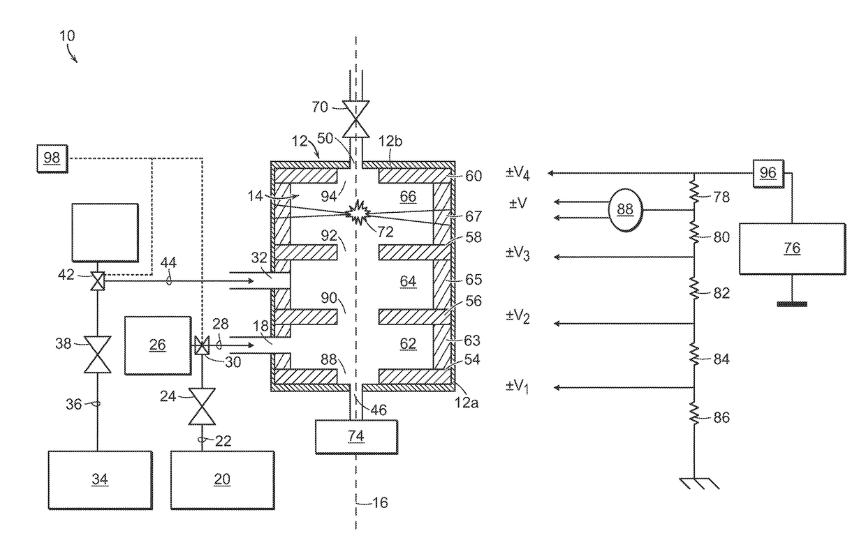
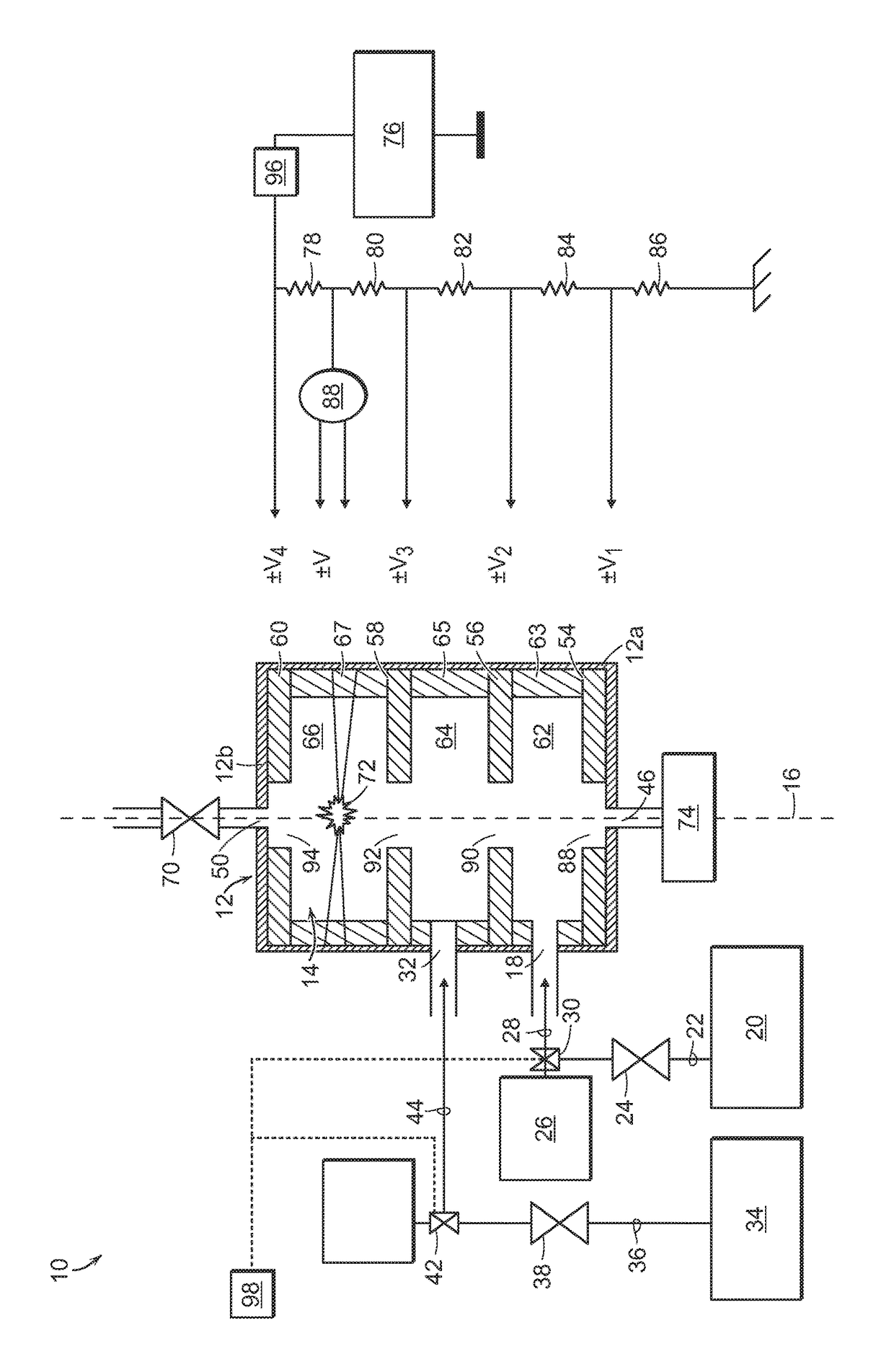
[0015]The invention generally is directed to a non-radioactive plasma ion source device and method of generating ions with a non-radioactive source. In one embodiment, the method is conducted under ambient conditions. Planar electrodes of the device, in combination with a discharger chamber, and first and second gas inlet chambers are aligned along a major longitudinal axis of a housing between a counterflow gas outlet and an analyte gas outlet. A method of operation of the non-radioactive plasma ion source device of the invention enables ionization of an analyte gas directed into either or both of the first and second gas inlet chambers with ions generated in the discharger chamber and cond...


PUM


Abstract

A non-radioactive plasma ion source device includes at least four planar electrodes that define at least three chambers, including a discharger chamber and at least two additional chambers aligned along a major longitudinal axis of the housing. A discharger ionizes at least one of a transport gas and a discharge gas to form ions in the discharger chamber that are directed by a homogeneous electric field generated by the planar electrodes toward an analyte gas outlet. Ionized species of at least one of the transport gas and the discharge gas that are not entrained by a counterflow gas stream are discharged from the discharger chamber to form a stream of ionized particles that ionize a sample gas and thereby form a stream of ionized analyte particles of the same polarity. The ionized analyte particles are entrained with the stream of ionized particles and pass through an analyte gas outlet to an analyzer.

Description

BACKGROUND OF THE INVENTION[0001]Ion mobility ionization type instruments (IMS) are employed to detect trace levels of chemicals in gas media. In IMS techniques, vapors of analyte molecules are ionized at ambient conditions, formed into ion species, and then identified by their coefficient of mobility. Conventional IMS ion identification is conducted in moderate direct current (DC) electric fields. In differential ion mobility spectrometry (DMS), which is a derivative of ion mobility technology, ion separation occurs by control of trajectories when ions move under the superimposed effect of a gas stream and a strong asymmetric waveform alternating current (AC) electric field. IMS and DMS are able to operate at atmospheric pressure conditions and, therefore, do not require cumbersome and high-power-consuming gas evacuating (pumping) equipment, thereby lending some portability to these instruments. Handheld prototypes of highly sensitive gas analyzers have been built, and numerous ite...

Claims


Application Information

Patent Timeline
IPC IPC(8): H01J49/16H01J49/10G01N27/62H01J49/04
CPCH01J49/105H01J49/168H01J49/0422G01N27/622G01N27/68
Inventor NAZAROV, ERKINJON G.MANOLAKOS, SPIROS Z.SINATRA, FRANCY L.POSTLETHWAITE, TIMOTHY A.MARKOSKI, KENNETH A.MORRIS, II, CLAYTON J.
Owner CHARLES STARK DRAPER LABORATORY
Why Eureka
Try Eureka