
Composition, system, and method for treating water systems

a technology of composition and water treatment, applied in the nature of treatment water, detergent compounding agents, cleaning using liquids, etc., can solve the problems of reducing the efficiency of treatment, reducing the cost of sewage treatment, and consuming around 700 billion gallons of water annually, so as to reduce the cost and risk, and reduce the effect of biofilm and scal

Active Publication Date: 2017-07-18
NCH CORP
View PDF71 Cites 3 Cited by
  • Summary
  • Abstract
  • Description
  • Claims
  • Application Information

AI Technical Summary

Benefits of technology

The invention is about a treatment composition that can effectively remove biofilm and scale from small water systems, such as reverse osmosis systems. The composition is made up of certain reagents that work synergistically to improve treatment performance. By using a concentrated liquid formula and solid form components that are dissolved on site, the composition minimizes the cost and risks associated with shipping and handling large volumes of liquid treatment chemicals. Additionally, the treatment method reduces damage to the materials in the water system being treated and optimizes cleaning while reducing energy consumption and increasing membrane life. The technical effects of the invention include improved treatment performance, reduced shipping and handling costs, and minimized damage to water systems.

Problems solved by technology

These systems consume around 700 billion gallons of water annually with a cost of $1.8 billion in sewage handling costs alone.
Such a treatment may also save on energy costs through the operation of clean heat exchange surfaces.
Fouling of heat exchange surfaces costs U.S. industry hundreds of millions of dollars every year and is directly related to an increase in energy consumption of almost 3 quadrillion Btus (quads) annually.
Many prior art treatment compositions and methods involve the use of liquid chemicals, typically shipped in large drums, which may make shipping and handling of the chemical compositions more difficult and expensive.
Additionally, many prior art treatment compositions and methods may damage the components of the water system being treated as the chemicals used are highly corrosive.
As these biofilm layers form they also accumulate other inorganic and organic debris that grow within the pipe restricting flow and causing blockages.
Similar issues, particularly with biofilms, are also encountered in drainage systems, such as hospital drains, industrial wastewater drains, and waterless urinals.
Even though some of these liquids are sterile when then enter the drain systems, it is virtually impossible to keep all fluids sterile when they enter the outside environment.
As they flow through the drainage system they accumulate naturally occurring micro flora and other heterotrophic microorganisms that, over time, result in the formation of biofilms along the surfaces of the walls of the pipes.
In hospitals, especially dialysis centers, this could present a direct risk of infection to patients.
Biofilms may also grow rapidly and result in clogged drains and piping in drainage systems.
They also typically involve added costs for protective gear for operators handling the chemicals and added training cots.
However, the disadvantage is that the mechanical removal of clogs and other biological deposits with these methods can be expelled into the environment putting the operator and other people in the vicinity at risk of exposure to biological pathogens.
Biofilm growth or biofouling is also a major issue in reverse osmosis systems, such as desalination plants.
Biofouling in a reverse osmosis system increases energy consumption in order to maintain the system's feed pressure, reduces permeate flux, and increases the amount of chemical feed needed to clean the membrane.
However, these products are either too corrosive and could destroy the integrity of the membrane, or highly toxic.

Method used


Image

  • Composition, system, and method for treating water systems
  • Composition, system, and method for treating water systems
  • Composition, system, and method for treating water systems

Examples


example 1b

[0086] The process of Example 1 was repeated with the use of a commercial dispersant on the MB-2128 present in the same concentrations as Example 1A, but without the treatment composition of the present invention. When the treated solution and biofilm were processed it was found that there was only a 3 log reduction in the biofilm and supernatant were achieved.

[0087]The results of Examples 1, 1A, and 1B show that using the maximum strength concentration of the reagents was highly effective at removing biofilm and eliminating microorganisms in the solution and in the biofilm. The minimum concentration showed some efficacy at removing biofilm and reducing microorganisms when used alone; however; when the treatment composition was used with a secondary biocide there was a marked improvement in performance with no viable bacteria being recovered in the sessile or planktonic states. In addition the performance of the minimum concentration solution when used with the secondary biocide out...

example 3a

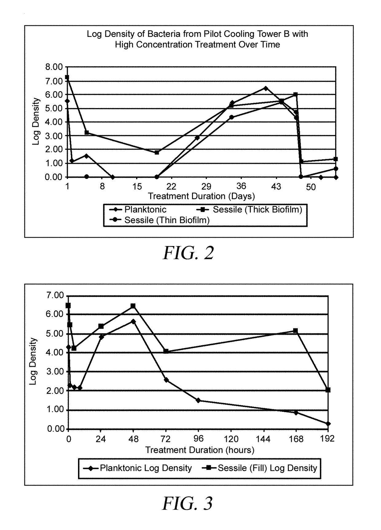
[0097] Treatment of the pilot cooling tower with the maximum concentration reagents in powdered form and a secondary biocide. At day 48, the cooling tower of Example 3 was treated again, this time with the maximum concentration reagents in powder form. This example demonstrates that there was no difference in performance between the power and liquid treatment compositions. As shown in FIG. 2, within three hours of the addition of the treatment composition in powdered form, both sessile and planktonic bacteria were reduced to levels below the detection limit and they remained at these low levels for over 1 week.

[0098]Corrosion evaluations on the maximum concentration for the treatment composition were performed on coupons in the corrosion rack in the cooling tower and in pot tests as previously described. The corrosion coupons in the coupon rack showed signs of corrosion after 24 hours. However, the galvanized steel coupons developed a waxy build up on the surface that increased in t...

example 5

[0110] Treatment of a 700 gallon cooling tower. Another experiment was conducted on a cooling tower that was considered to be a clean tower. A Marley 700 gallon cooling tower was identified and inspected for signs of visible contamination. It was noted that the water was clear, there was some brown deposits on the fill in the water, and there was a small amount of calcium carbonate scale on the outer surfaces of the fill. One week prior to starting the experiment, the conventional biocide treatment program was stopped. Microbial analysis of the water and brown deposit on the fill prior to starting the experiment showed counts of 1×10⁴ cfu per ml and 1×10⁴ cfu per cm, respectively, which are well within the specifications for this tower to be considered clean.

[0111]The treatment composition concentration was the same as that used in the previous experiments with the only change being the surfactant, which was switched to didecyldimethyl ammonium chloride. Prior to treatment a 17 ppm ...


PUM

PropertyMeasurementUnit
linear velocityaaaaaaaaaa
total volumeaaaaaaaaaa
treatment timeaaaaaaaaaa

Abstract

A composition for treating a water system or membrane fluid system, such as a reverse osmosis system, to remove scale, microorganisms and biofilm, and corrosion by-products. The composition comprises chelating agents and a surfactant. The composition may be a solid dissolved by water or solvent in the system being treated or may be a pre-mixed foam or aerosol. A method for using such a treatment composition comprises contacting the treatment composition with substantially all parts of the water system and draining the treatment composition from the system before resuming normal operations. For certain systems, the method also comprises draining some existing water in the water system to remove prior treatment compositions and filling or rinsing the system with fresh water prior to adding the treatment composition.

Description

CROSS-REFERENCE TO RELATED APPLICATION[0001]This application is a continuation-in-part of U.S. application Ser. No. 13 / 745,211 filed on Jan. 18, 2013, now U.S. Pat. No. 9,452,457, which claims the benefit of U.S. provisional patent application No. 61 / 587,966 filed Jan. 18, 2012.BACKGROUND OF THE INVENTION[0002]1. Field of the Invention[0003]This invention relates to a treatment composition, system, and method for treating water systems for scale, biofilm and microbial growth, and corrosion. This invention is particularly useful in anthropogenic cooling and chilled water applications, such as cooling towers, and in drain systems, such as floor drains, hospital drains and waterless urinals, and for treating reverse osmosis membrane systems.[0004]2. Description of Related Art[0005]Anthropogenic water systems are critical components commonly found in most of the world's energy producing facilities, industrial and manufacturing plants, hospitals, and other institutional complexes and bui...

Claims


Application Information

Patent Timeline
Patent Type & Authority Patents(United States)
IPC IPC(8): B08B7/04B01D61/02B01D61/14A01N37/36B08B9/08C02F1/50B01D65/08A01N59/00C11D3/20C11D3/48C02F1/68B01D61/00C02F1/44C11D3/33C11D1/38C02F1/76C02F1/00B08B9/00B08B3/04C02F101/30C02F103/02
CPCB01D65/08A01N37/36A01N59/00B01D61/002B01D61/025B01D61/027B01D61/145B01D61/147B08B9/0856C02F1/50C02F1/68C02F1/683C11D3/2086C11D3/48A01N25/30A01N33/12B08B3/04B08B9/00C02F1/001C02F1/008C02F1/441C02F1/442C02F1/444C02F1/445C02F1/685C02F1/687C02F1/76C02F1/766C02F2101/30C02F2103/023C02F2303/02C02F2303/04C02F2303/08C02F2303/20C02F2303/22C02F2305/04C02F2305/14C02F2307/08C11D1/38C11D3/33A01N2300/00
Inventor DENVIR, ADRIANEDFORD, JAMES GREGORYDELEGARD, ANGELA LBOYETTE, SCOTT M
Owner NCH CORP
Learn More