Compac X-ray source for semiconductor metrology

a semiconductor and x-ray source technology, applied in the field of metalrology systems and methods, can solve the problems of difficult optical radiation penetration to the bottom layer, difficult characterization, and more difficult characterization, so as to improve measurement performance, low noise, and low noise

Active Publication Date: 2017-11-21
KLA TENCOR TECH CORP
View PDF18 Cites 6 Cited by
  • Summary
  • Abstract
  • Description
  • Claims
  • Application Information

AI Technical Summary

Benefits of technology

[0016]In a further aspect, the compact x-ray source is tunable, allowing for adjustments of both the wavelength and flux of the generated x-ray radiation. In some examples, the electron beam energy generated by the compact electron beam accelerator is controlled to tune the wavelength of x-ray radiation emitted from the undulator. In some other examples, operational parameters of the undulator are controlled to tune the wavelength of the x-ray radiation incident on

Problems solved by technology

As devices (e.g., logic and memory devices) move toward smaller nanometer-scale dimensions, characterization becomes more difficult.
Devices incorporating complex three-dimensional geometry and materials with diverse physical properties contribute to characterization difficulty.
For example, modern memory structures are often high-aspect ratio, three-dimensional structures that make it difficult for optical radiation to penetrate to the bottom layers.
As a result, the parameters characterizing the target often cannot be reliably decoupled with available measurements.
Optical radiation is often unable to penetrate layers constructed of these materials.
As a result, measurements with thin-film scatterometry tools such as ellipsometers or reflectometers are becoming increasingly challenging.
In response, more complex optical tools have been developed.
However, these approaches have not reliably overcome fundamental challenges associated with measurement of many advanced targets (e.g., complex 3D structures, structures smaller than 10 nm, structures employing opaque materials) and measurement applications (e.g., line edge roughness an

Method used


Image

  • Compac X-ray source for semiconductor metrology
  • Compac X-ray source for semiconductor metrology
  • Compac X-ray source for semiconductor metrology

Examples


embodiment 180

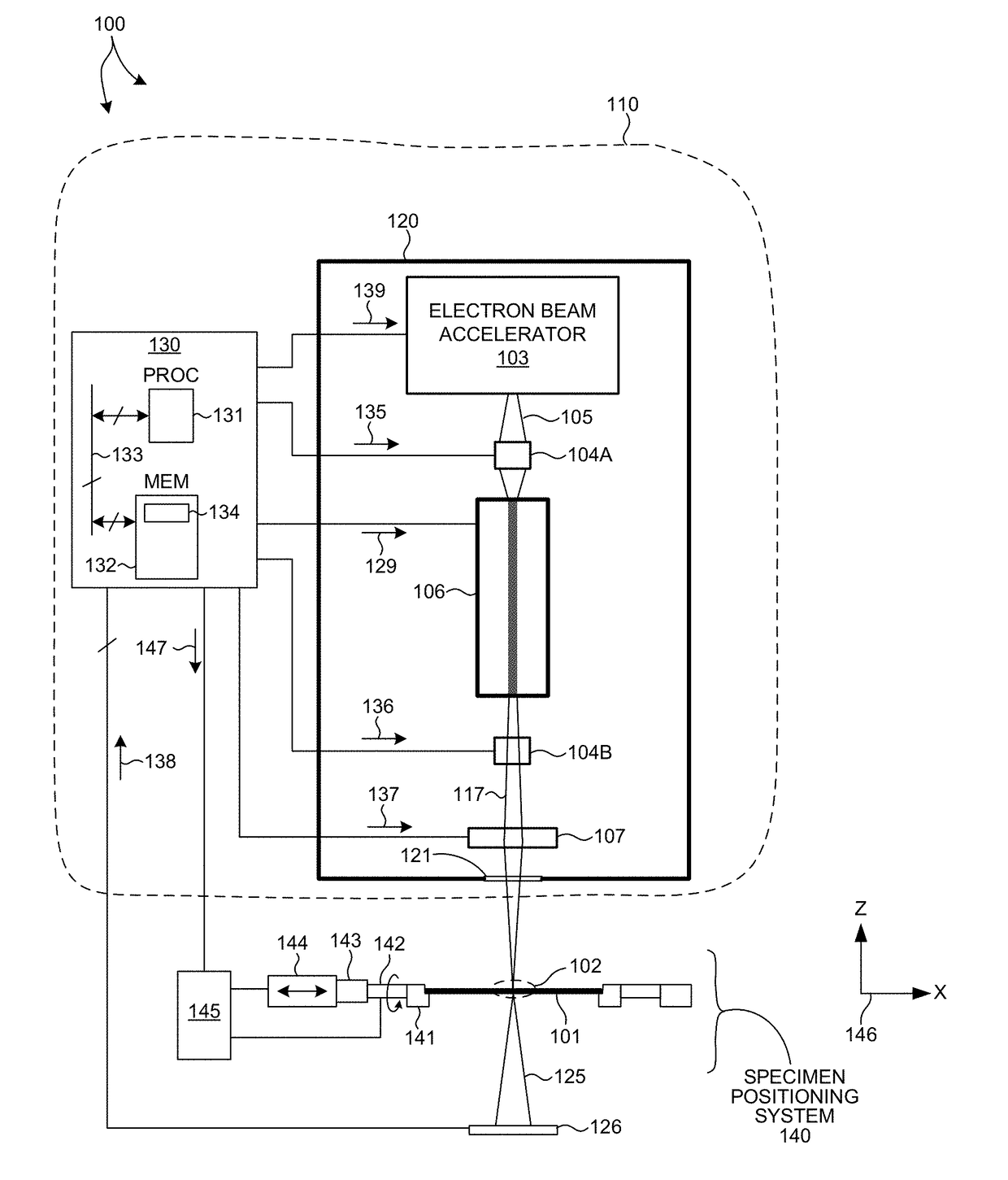
[0057]In some other embodiments, undulator 106 is a semiconductor based dielectric undulator. FIG. 5 illustrates a magnetic undulator based on a dielectric structure. Undulator 180 includes dielectric grating structures 181 and 182 placed on opposite sides of a stream of electrons 105. The gratings are aligned such that an alternating electric field is generated along the length of the undulator 180 when high intensity laser light 183 is passed through the dielectric structures 181 and 182. The stream of electrons 105 passing through undulator 180 is forced to undergo oscillations, and thus radiate energy. While dielectric undulators have relatively low undulator deflection parameter values (e.g., K<0.01), dielectric gratings can be produced with periods on the order of several microns. Thus, a dielectric undulator structure can generate very short wavelength radiation with a very small structure. For example, electron beam energy of 110 MeV is needed to generate x-ray radiation at ...

embodiment 190

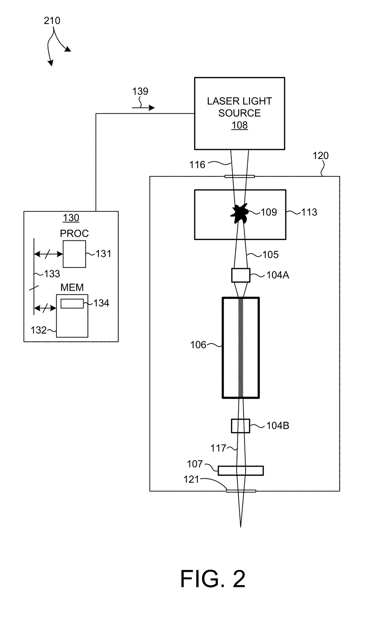
[0061]FIG. 6 illustrates an optical undulator based on a four-mirror optical resonator 191 including focusing mirror elements 191A-D. Laser light 193 from a laser light source 192 is pumped into optical resonator 191 to generate a standing wave in the middle of the optical resonator 191. The standing wave creates an alternating magnetic field. The stream of electrons 105 passing through the standing wave in the middle of optical resonator 191 is forced to undergo oscillations, and thus radiate energy. Although, optical resonator 191 is described with reference to a four-mirror optical resonator, in general, any optical resonator structure may be contemplated.

[0062]In one example, light generated from a 10 kW phase-locked CO2 laser with a wavelength of 10.6 micrometers is inserted into an optical storage cavity with a continuous wavelength circulating power of 3 Gigawatts. At focus, the beam radius is 45 micrometers, and the laser strength parameter of the optical cavity, a0, is 0.1....


PUM


Abstract

Methods and systems for realizing a high brightness, compact x-ray source suitable for high throughput, in-line x-ray metrology are presented herein. A compact electron beam accelerator is coupled to a compact undulator to produce a high brightness, compact x-ray source capable of generating x-ray radiation with wavelengths of approximately one Angstrom or less with a flux of at least 1e10 photons/s*mm^2. In some embodiments, the electron path length through the electron beam accelerator is less than ten meters and the electron path length through the undulator is also less than 10 meters. The compact x-ray source is tunable, allowing for adjustments of both wavelength and flux of the generated x-ray radiation. The x-ray radiation generated by the compact x-ray source is delivered to the specimen over a small spot, thus enabling measurements of modern semiconductor structures.

Description

CROSS REFERENCE TO RELATED APPLICATION[0001]The present application for patent claims priority under 35 U.S.C. §119 from U.S. provisional patent application Ser. No. 61 / 790,862, entitled “Metrology Apparatus Using A Compact X-Ray Source,” filed Mar. 15, 2013, the subject matter of which is incorporated herein by reference in its entirety.TECHNICAL FIELD[0002]The described embodiments relate to metrology systems and methods, and more particularly to methods and systems for improved illumination.BACKGROUND INFORMATION[0003]Semiconductor devices such as logic and memory devices are typically fabricated by a sequence of processing steps applied to a specimen. The various features and multiple structural levels of the semiconductor devices are formed by these processing steps. For example, lithography among others is one semiconductor fabrication process that involves generating a pattern on a semiconductor wafer. Additional examples of semiconductor fabrication processes include, but ar...

Claims


Application Information

Patent Timeline
IPC IPC(8): H05G2/00
CPCH05G2/00H05G2/008G21K7/00
Inventor BAKEMAN, MICHAEL S.SHCHEGROV, ANDREI V.
Owner KLA TENCOR TECH CORP
Why Eureka
Try Eureka