

Solid electrolytic capacitor and production method thereof
A technology of solid electrolysis and solid electrolyte layer, which is applied in the direction of solid electrolytic capacitors, electrolytic capacitors, capacitors, etc., can solve the problems of large intervals, reduced area of dielectric materials, and reduced apparent ratio of capacitance, so as to achieve high reflow temperature and prevent The increase in leakage current and the effect of increasing the apparent ratio of capacitance
- Summary
- Abstract
- Description
- Claims
- Application Information
AI Technical Summary
Problems solved by technology
Method used
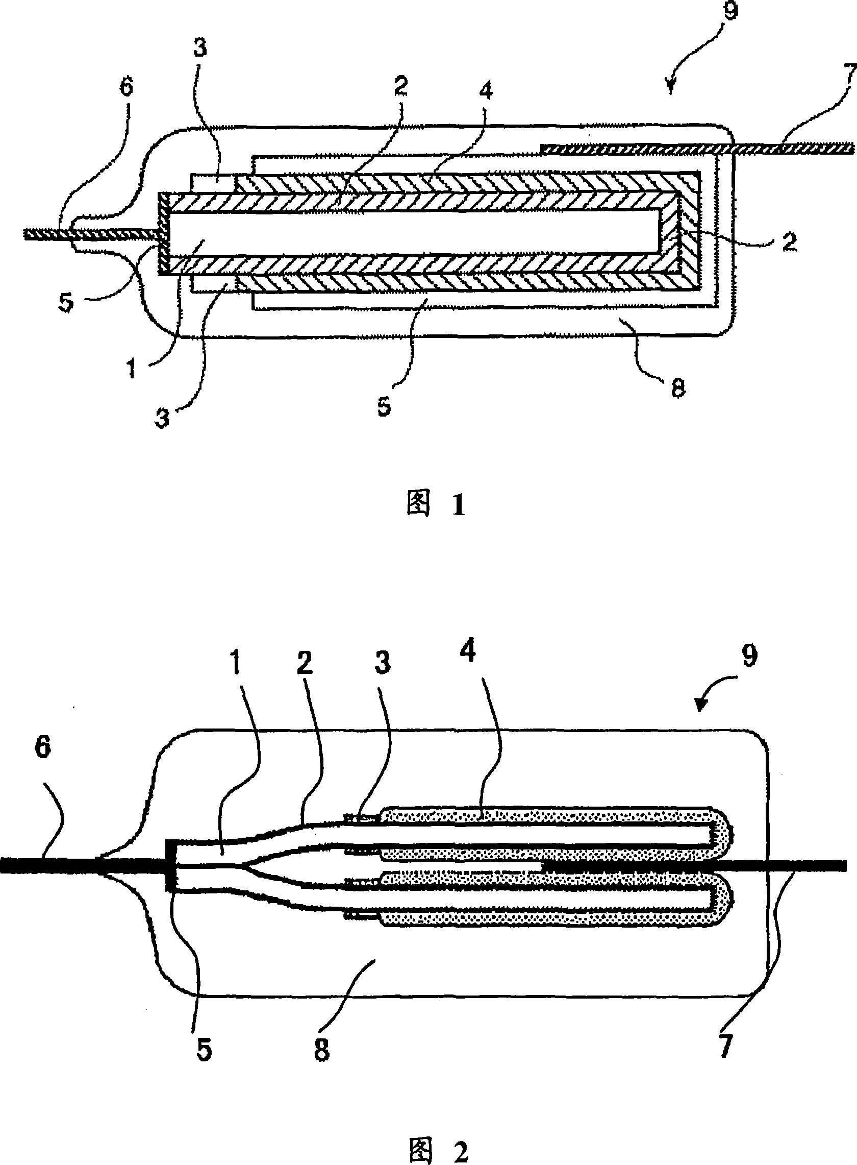
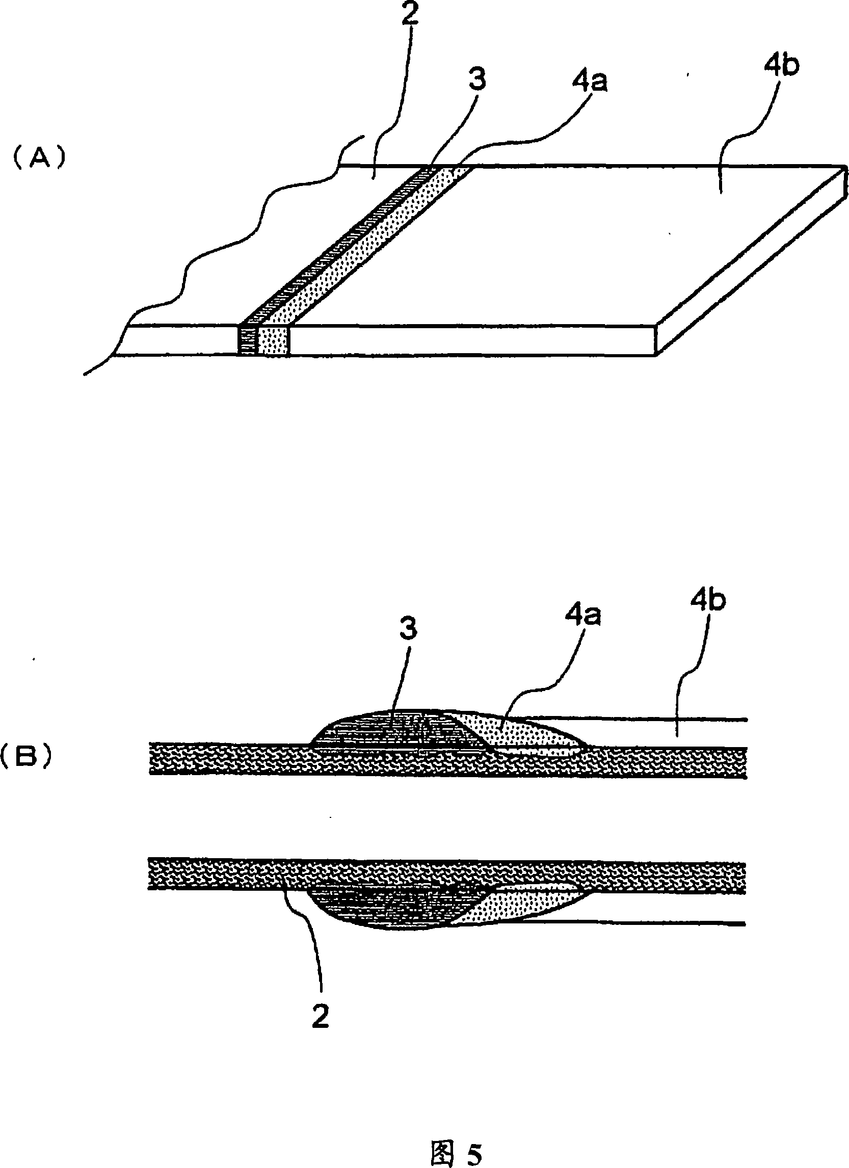
Image

Examples
Embodiment 1
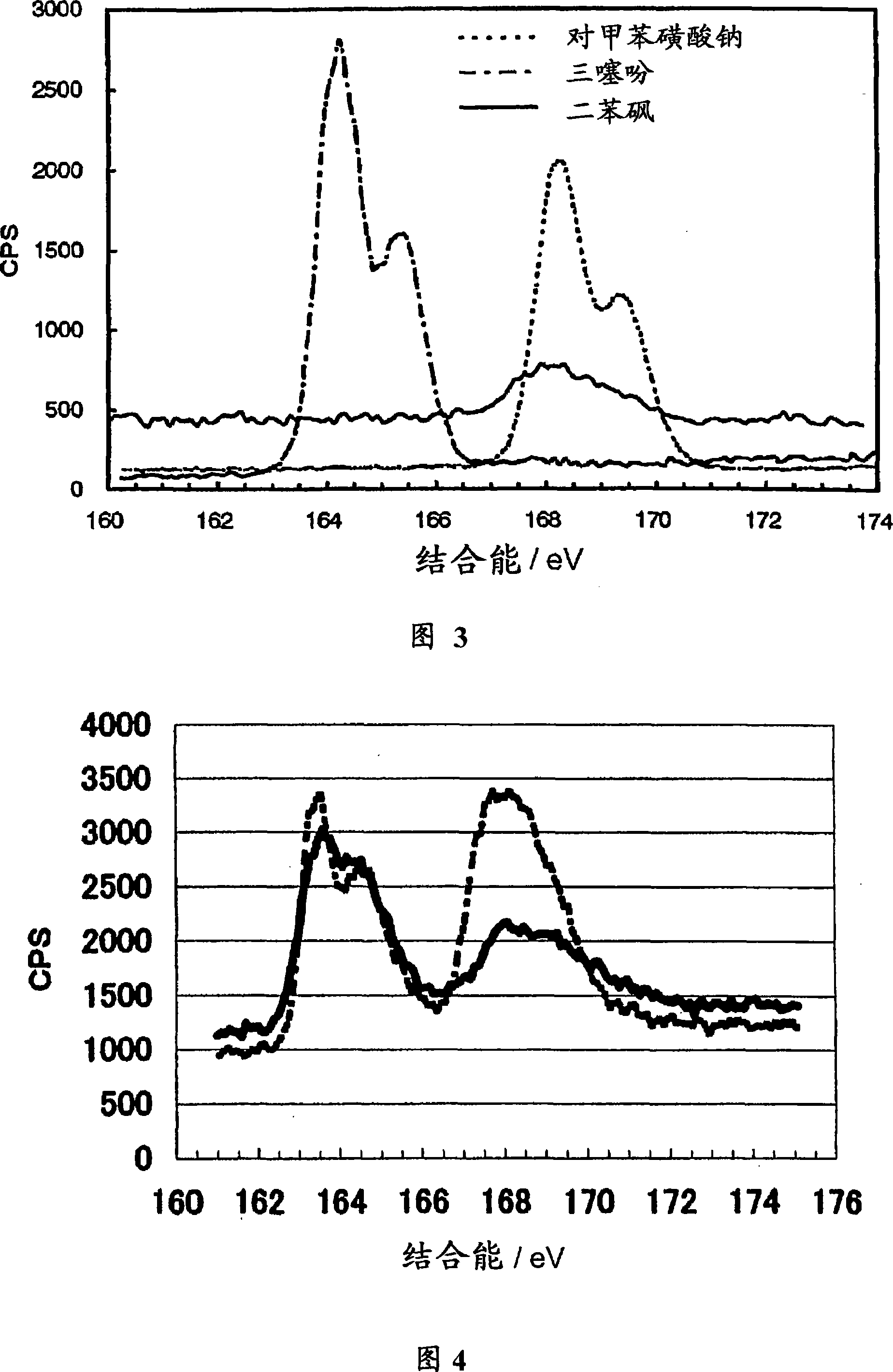
[0310] A chemically formed aluminum foil (thickness: 100 µm) was cut into small pieces of size 3.5 mm (minor axis direction) x 11 mm (major axis direction). A polyimide solution was hoop-coated with a width of 1 mm on both surfaces of the foil so as to divide the surface into two 5 mm sections in the long-axis direction, and then dried to provide a mask. A portion (cathode constituting portion) having a size of 3.5 mm×5 mm of the chemically formed foil thus obtained was immersed in a 10% by mass ammonium adipate aqueous solution, and the cut portion was chemically formed by applying a voltage of 3.8 V to form Dielectric material oxide film. Thereafter, this part of the aluminum foil thus treated was dipped in the conductive composition 1 for 5 seconds, and dried at room temperature for 5 minutes. The surface of the dielectric layer formed on the layer having pores in the chemically formed aluminum foil after drying was measured by X-ray photoelectron spectroscopy (XPS), the S...
Embodiment 2
[0316] A portion (cathode constituting portion) having a size of 3.5 mm x 5 mm of chemically formed aluminum foil (where a mask was provided in the same manner as in Example 1) was treated in the same manner as in Example 1 and cut open. Part of the chemical formation to form a dielectric oxide film. The chemically formed part was then dipped in the conductive composition 1 for 5 seconds, dried at room temperature for 5 minutes, and then subjected to a dehydrogenation condensation reaction at 300°C for 15 minutes to allow crosslinking to proceed, thereby forming its own on the surface of the dielectric film. Self-doping conductive polymer with crosslinks between polymer chains (step 1).
[0317] Furthermore, a solid electrolyte was formed in the same manner as in Example 1 except that this operation was repeated once more.
[0318] Then, again chemical formation, coating of carbon paste and silver paste, lamination, connection of cathode lead end, encapsulation with epoxy res...
Embodiment 3
[0320] A part (cathode constituting part) having a size of 3.5 mm x 5 mm of the chemically formed aluminum foil (where a mask was provided in the same manner as in Example 1) was treated in the same manner as in Example 1 and cut open. Part of the chemical formation to form a dielectric oxide film. A total of 30 capacitors were completed in the same manner as in Example 1, except that the chemically formed aluminum foil was dipped in the conductive composition 2 for 5 seconds and dried at room temperature for 5 minutes, followed by a dehydrogenation condensation reaction at 250 °C 30 minutes to allow crosslinking to proceed, thereby forming a self-doping type conductive polymer having crosslinks between its polymer chains on the surface of the dielectric film. The characteristics of the obtained capacitor element were evaluated in the same manner as in Example 1. Tables 1 and 2 show these results.
PUM
| Property | Measurement | Unit |
|---|---|---|
| thickness | aaaaa | aaaaa |
| thickness | aaaaa | aaaaa |
| particle size | aaaaa | aaaaa |
Abstract
Description
Claims
Application Information