

Nitrogen doped carbon nanotube and preparation method thereof, and carbon nanotube element
A carbon nanotube and nanotube technology, applied in the field of preparing nitrogen-doped carbon nanotubes, can solve problems such as strong corrosion, and achieve the effect of being beneficial to industrial production and high product purity
- Summary
- Abstract
- Description
- Claims
- Application Information
AI Technical Summary
Problems solved by technology
Method used
Image

Examples
preparation example Construction
[0047] A typical FET is fabricated as follows. As mentioned above, the original product of the nitrogen-doped carbon nanotubes is usually entangled tube bundles, first they are fully ultrasonically dispersed in an organic solvent (such as ethanol), and then the liquid drops to the surface layer as SiO2 On a silicon wafer, a large number of metal electrodes have been fabricated by conventional photolithography, metal evaporation or screen printing. The presence of individual carbon nanotubes or bundles of tubes connecting the two electrodes was then examined under an atomic force microscope (AFM). These two electrodes will serve as the source and drain of the FET to be fabricated. The distance between the two electrodes is typically 100 nm, and the distance between the electrodes varies in the range of 0.1 to 1 micron, for example. SiO 2 Another electrode below the layer or the doped silicon substrate is used as the gate electrode of the FET to apply a gate voltage to control...
example 1
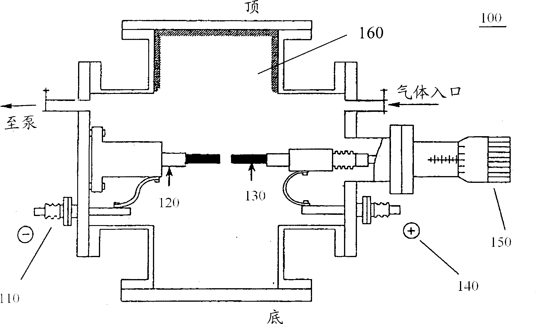
[0052] by figure 1 In the electric arc furnace 100 shown, the anode 130 is a graphite rod with a length of 10 cm and a diameter of 8 mm, and the cathode 120 is a graphite rod with a diameter of 16 mm. Melamine was used as nitrogen source. A small hole with an inner diameter of 6 mm and a depth of 8 mm is drilled at one end of the graphite rod of the anode, and the hole is filled with a mixture of graphite powder, Y / Ni (=1:4.2) powder as a metal catalyst and melamine as a nitrogen source, of which three The mass ratio of the latter is roughly 15:5:1. The filling in the above hole is compacted. Then, the electric arc furnace 100 is evacuated, and then the vacuum valve is closed, and helium gas at a pressure of 700 Torr is introduced. After turning on the power, the distance between the cathode 120 and the anode 130 is adjusted to generate a stable arc discharge, the current is controlled at about 100A, and the voltage is kept at about 30V. After several minutes of discharge,...
example 2
[0057] The electric arc furnace that example 2 adopts and discharge condition are identical with example 1, except using urea (CO (NH 2 ) 2 ) as a source of nitrogen. The nitrogen-doped carbon nanotubes collected after arc discharge are called sample 2.
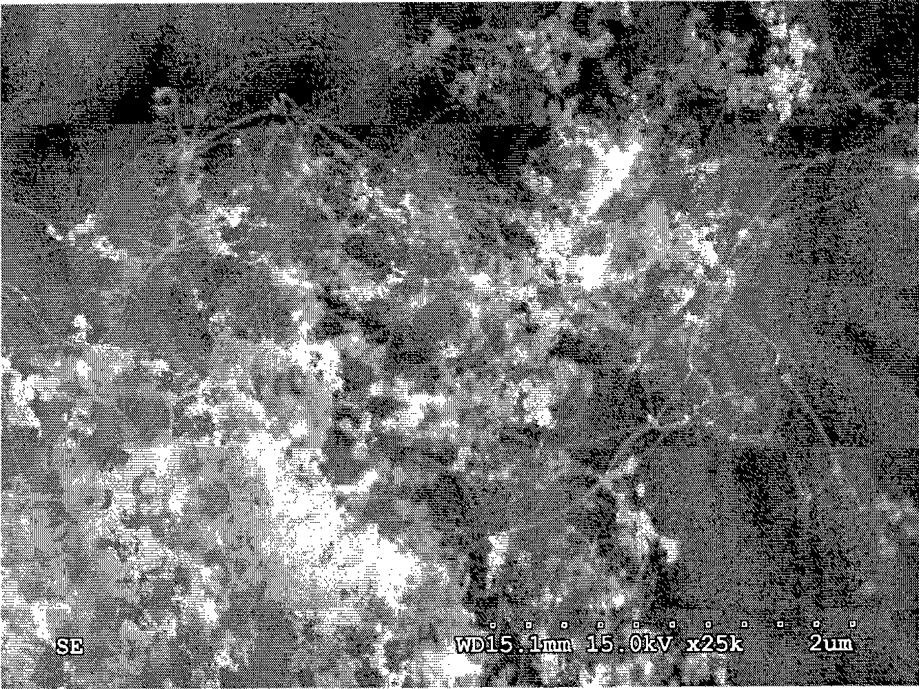
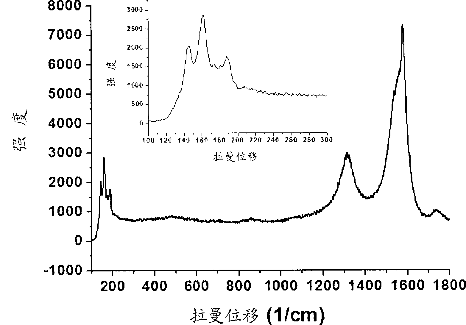
[0058] Figure 4A The SEM photo of sample 2 is shown, Figure 4B The Raman spectrum of sample 2 is shown. exist Figure 4A It can be seen from the SEM photos of the obtained carbon nanotubes that the obtained carbon nanotubes are assembled into bundles and grow into filaments with a length ranging from several microns to tens of microns, and the tube bundles are entangled with each other. Most of the products are single-walled carbon nanotubes. The product also contains randomly distributed spherical nanoparticles, but the content of these impurities can be visually observed Figure 2A The content in the shown sample 1 is small.
[0059] From Figure 4B It can be seen from the Raman spectrum of these carbon nanotubes...
PUM
| Property | Measurement | Unit |
|---|---|---|
| diameter | aaaaa | aaaaa |
| diameter | aaaaa | aaaaa |
Abstract
Description
Claims
Application Information