Method for depriving nitric oxide by plasma cooperating with low-temperature catalytic oxidation NO

A plasma and low-temperature catalysis technology, applied in separation methods, chemical instruments and methods, dispersed particle separation, etc., can solve the problems of secondary pollution, easy leakage, and high reaction temperature, and achieves a small footprint and no secondary pollution. , the effect of a wide concentration range

Inactive Publication Date: 2010-07-14
KUNMING UNIV OF SCI & TECH
View PDF6 Cites 20 Cited by
  • Summary
  • Abstract
  • Description
  • Claims
  • Application Information

AI Technical Summary

Problems solved by technology

[0003] At present, the ammonia selective catalytic reduction method is mostly used to purify the nitrogen oxides in the stationary source exhaust gas. Although the ammonia selective catalytic reduction method has been successfully used to remove nitrogen oxides emitted from stationary sources (such as thermal power plants), but The amount of ammonia needs to be accurately measured and controlled, and ammonia is highly corrosive, and it is easy to leak to cause secondary pollution. The economizer and air preheater are assembled together, which is not conducive to the installation of the SCR reactor, so the existing SCR process is difficult to be directly applied to the boiler in our country
[0004] Chinese patent CN 1803257A discloses a method for removing nitrogen oxides in coal-fired power plants using amino substances as reducing agents. 35-40% of the nitrogen oxides in the gas, the unreacted amino substances enter the reactor with the flue gas, and on the surface of the catalyst, the amino substances react with the nitrogen oxides again, and the nitrogen oxide reduction rate can reach more than 90%, but The reaction temperature of this method is relatively high, and the amino reducing agent is introduced, so there are problems of leakage and equipment corrosion
Chinese patent CN 1613544A discloses a method for plasma-enhanced methane selective catalytic reduction of nitrogen oxides, which realizes the use of plasma synergistic catalytic reduction at room temperature to 350 °C, and only uses catalytic reduction when the temperature exceeds 350 °C. Although the input power of this method is Lower, but still have to heat up, higher energy consumption

Method used


Image

  • Method for depriving nitric oxide by plasma cooperating with low-temperature catalytic oxidation NO

Examples


Embodiment 1

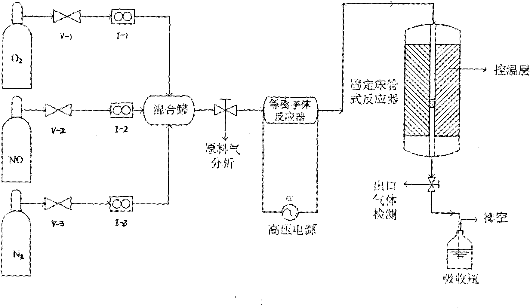
[0012] Coaxial dielectric barrier reactor plasma reactor has corundum tubes with inner and outer diameters of 20mm and 25mm respectively. A stainless steel electrode with a diameter of 10mm is inserted in the center of the corundum tube. The outer wall of the corundum tube is wound with stainless steel mesh as a high-voltage electrode. Low voltage electrode, plasma input voltage is 10V, current is 0.2A; NO volume fraction is 5×10 -4 , O 2 3%, N 2 It is balance gas, the total flow rate of mixed gas is 200ml / min, and the space velocity is 51000h -1 . Activate the mixed gas to be treated through a plasma reactor, and the activated mixed gas passes through a fixed-bed reactor equipped with MnOx-CP catalyst (0.2 g), and is heated to 250 ° C by a temperature control layer to quantitatively oxidize it to NO 2 , and then the gas enters the lye absorption bottle for absorption and utilization. The removal rate of NO reached 82% at 150°C.

Embodiment 2

[0014] Coaxial dielectric barrier reactor plasma reactor has corundum tubes with inner and outer diameters of 20mm and 25mm respectively. A stainless steel electrode with a diameter of 10mm is inserted in the center of the corundum tube. The outer wall of the corundum tube is wound with stainless steel mesh as a high-voltage electrode. Low voltage electrode, plasma input voltage is 22V, current is 0.5A. NO volume fraction is 5×10 -4 , O 2 3%, N 2 It is balance gas, the total flow rate of mixed gas is 200ml / min, and the space velocity is 12000h -1 ; The mixed gas to be treated is activated by a plasma reactor, and the activated mixed gas is passed through a fixed-bed reactor equipped with a MnOx-CA-400 catalyst (0.6 gram), and is heated to 250° C. by a temperature control layer to quantitatively oxidize to NO 2 , and then the gas enters the lye absorption bottle for absorption and utilization. The removal rate of NO reached 41% at 50℃.

Embodiment 3

[0016] Coaxial dielectric barrier reactor plasma reactor has corundum tubes with inner and outer diameters of 20mm and 25mm respectively. A stainless steel electrode with a diameter of 10mm is inserted in the center of the corundum tube. The outer wall of the corundum tube is wound with stainless steel mesh as a high-voltage electrode. Low voltage electrode, plasma input voltage is 70V, current is 1.5A; NO volume fraction is 5×10 -4 , O 2 3%, N 2 It is balance gas, the total flow rate of mixed gas is 200ml / min, and the space velocity is 60000h -1 ; The mixed gas to be treated is activated by the plasma reactor, and the activated mixed gas is passed through the MA-MnOx / TiO 2 Catalyst (0.15g) in a fixed bed reactor, heated to 250°C with a temperature control layer to quantitatively oxidize to NO 2 , and then the gas enters the lye absorption bottle for absorption and utilization. The removal rate of NO reached 56% at 100℃.

[0017] Catalyst preparation: Co-precipitation met...


PUM


Abstract

The invention relates to a method for depriving nitric oxide by plasma cooperating with low-temperature catalytic oxidation NO, which is characterized by comprising the following steps of: controlling the airspeed of a mixed gas which contains NO and O2 and is to be processed between 10,000 h<-1> and 60,000 h<-1>; activating through a plasma reactor; and quantificationally oxidizing NOx contained in the activated mixed gas into NO2 at 50-150 DEG C through a fixed bed reactor containing a manganese-base oxide catalyst. Compared with the prior art, the invention has simple process, less adverse effects of CO, CO2 and SO2 impurity components contained in the gas and wide NOX processing concentration range, quantificationally coverts the NO into the NO2 at lower temperature and further absorbs and utilizes the NO2, thereby achieving the resource processing; in addition, the invention has low energy consumption, simple process, small occupying area, no secondary pollution, and the like.

Description

technical field [0001] The invention relates to the technical field of air pollution purification, in particular to a method for removing nitrogen oxides by utilizing low-temperature plasma to cooperatively catalyze and oxidize NO under normal temperature conditions. Background technique [0002] Nitrogen oxides (NOx) are one of the main air pollutants and an important precursor for inducing photochemical smog and acid rain. Now the world's NO emissions have reached 35-58Mt / a, more than 95% of which come from the combustion process of fossil fuels. NO accounts for 90% to 95% of the total NOx in combustion flue gas. my country's NOx mainly comes from industrial combustion processes and vehicle engines. Since my country's energy structure is still dominated by coal, and most of them are directly burned, NOx produced by combustion is an important polluting gas. [0003] At present, the ammonia selective catalytic reduction method is mostly used to purify the nitrogen oxides ...

Claims


Application Information

Patent Timeline
Patent Type & Authority Applications(China)
IPC IPC(8): B01D53/86B01D53/56
CPCY02A50/20
Inventor 唐晓龙李凯易红宏于丽丽杨丽娜叶智青
Owner KUNMING UNIV OF SCI & TECH
Why Eureka
Try Eureka