Ceramic coating ozone generating tube and preparation method thereof

An ozone generating tube and ceramic coating technology, applied in ozone preparation, ceramics, coating and other directions, can solve the problems of low dielectric strength, difficult process realization, environmental pollution, etc., and achieve good oxidation resistance and corrosion resistance, and the preparation conditions are not harsh. , Guarantee the effect of technical effect

Inactive Publication Date: 2011-08-24
SUZHOU ZHISHUN SURFACE TECH
View PDF2 Cites 0 Cited by
  • Summary
  • Abstract
  • Description
  • Claims
  • Application Information

AI Technical Summary

Problems solved by technology

[0004] At present, in my country, the dielectric materials of ozone tubes used in ozone generators are still mainly quartz glass and enamel. Due to the disadvantages of low dielectric strength and easy breakdown of these dielectric materials, large-scale ozone generators have high energy consumption and ozone Low yield, large equipment volume and high failure rate of ozone tube greatly affect the reliable operation of the whole machine
Since the late decades of the last century, France and Germany have devoted themselves to research on the ozone tube dielectric material and its preparation method, but, perhaps for the sake of technical secrecy, there is no detailed report in the media such as literature
[0005] The ceramic ozone tube technical scheme disclosed by the aforementioned CN2741957Y adopts the ceramic dielectric layer of 1-2mm plated on the outer wall of the inner electrode in the mode of plating. Pollution; according to the teaching of the patent specification, it is difficult to coat the ceramic powder material on the outer wall of the inner electrode, because the ceramic is non-conductive, so it is difficult to realize in the process
[0006] Invention Patent Application Publication No. CN101289168A introduces a new type of ozone tube, which is made of polytetrafluoroethylene and is set outside the inner electrode. Because the material used in this scheme is polytetrafluoroethylene, the dielectric constant will not show satisfactory results
However, no corresponding technical revelation has been given in the published literature so far, and no relevant reports of success have been heard.
The current situation is that the ozone generating tubes for large-scale ozone generators mainly rely on foreign imports, and the price is very expensive. Therefore, from the perspective of industrial independence, it is necessary to explore

Method used


Image

  • Ceramic coating ozone generating tube and preparation method thereof
  • Ceramic coating ozone generating tube and preparation method thereof

Examples


Embodiment 1

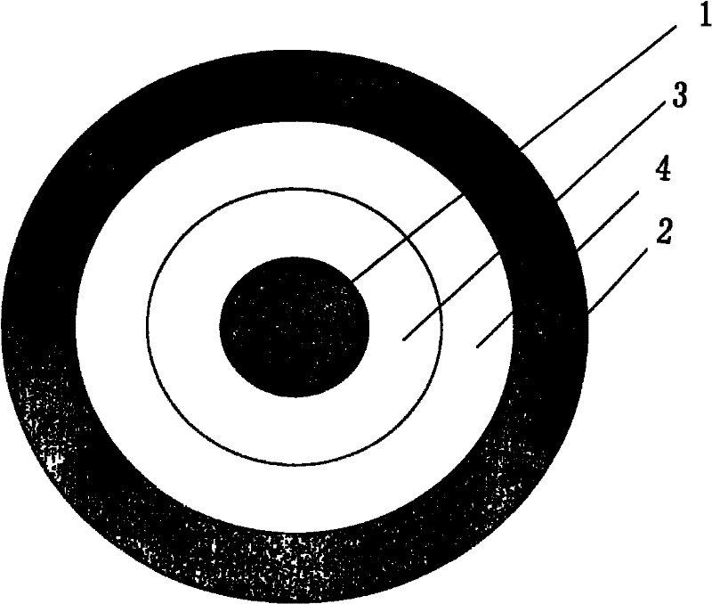
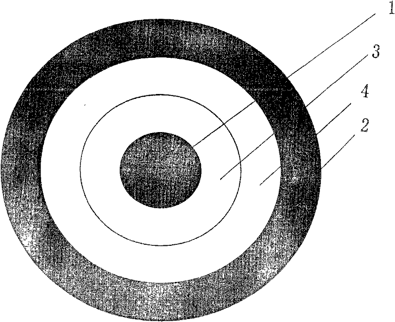
[0027] Please refer to the accompanying drawings, an embodiment structure of the ceramic coating ozone generating tube of the hospital is given, including an internal electrode 1, an external electrode 2, a dielectric layer 3 combined with the outer surface of the internal electrode 1 and being formed between the dielectric layer 3 and the outer surface. The discharge gap 4 between the electrodes 2, wherein the dielectric layer 3 is a ceramic dielectric insulating layer, the specific steps of the preparation method are as follows:

[0028] A) cleaning, putting the internal electrode 1 into an ultrasonic cleaning machine for cleaning, so that the outer surface of the internal electrode 1 forms a clean surface, and the cleaned internal electrode 1 is obtained;

[0029] B) Surface pretreatment, using a sandblasting device to spray 20# white corundum sand on the outer surface of the inner electrode 1, that is, the outer circular surface, so that the outer surface of the inner elect...

Embodiment 2

[0034] Change the current of the plasma spraying equipment in step C) to 430A, the flow rate of argon gas to 150L / min, the flow rate of hydrogen gas to 28L / min, the powder feeding rate to 50g / min, the distance between the nozzle and the workpiece Change it to 20cm, and the ceramic dielectric insulating coating in step D) i.e. Al 2 o 3 The thickness of the dielectric layer 3 is changed to 0.4mm, Al 2 o 3 The compressive strength of the coating is tested to be 10.5-11KV / mm. All the other are the same as the description to embodiment 1.

Embodiment 3

[0036] Only change the spraying material in step C) to use mass percentage content instead, that is, the Y with a purity of > 98% 2 o 3 , the current of the plasma spraying machine is changed to 400A, the flow rate of argon gas is changed to 110L / min, the flow rate of hydrogen gas is changed to 18L / min, the amount of powder feeding is changed to 20g / min, the distance between the nozzle and the workpiece is changed to 10cm, and the In the step D), the ceramic dielectric insulating coating is Y 2 o 3 The thickness of the dielectric layer 3 is changed to 0.3mm, Y 2 o 3 The compressive strength of the coating is tested to be 19.5-19.9KV / mm. All the other are the same as the description to embodiment 1.


PUM

PropertyMeasurementUnit
thicknessaaaaaaaaaa
thicknessaaaaaaaaaa
thicknessaaaaaaaaaa

Abstract

The invention discloses a ceramic coating ozone generating tube and a preparation method thereof, which belong to the technical field of ozone generating devices. The tube comprises an internal electrode, an external electrode, a dielectric layer bonded on the external surface of the internal electrode and a discharge gap formed between the dielectric layer and the external electrode, and is characterized in that: the dielectric layer is a ceramic dielectric insulating coating. The ceramic coating ozone generating tube has the advantages of high dielectric constant, high insulating strength (voltage resists up to 10,000 to 12,000V / mm) and high oxidation corrosion resistance. The provided preparation method has fewer process steps and mild preparation conditions, can ensure the technical effect of the ceramic coating ozone generating tube and is suitable for industrial batch production.

Description

technical field [0001] The invention belongs to the technical field of ozone generators, in particular to a ceramic-coated ozone generator and a preparation method for the ceramic-coated ozone generator. Background technique [0002] Ozone generators, especially large-scale ozone generators, are widely used in industry. More specifically, they have good application prospects in water treatment, chemical medicine, papermaking and environmental protection industries. [0003] The mechanism of action of the ozone generator is not unfamiliar to the industry, and it can also be understood in more detail through the description of the background technology column of the ceramic ozone tube disclosed in the Chinese utility model patent authorization announcement number CN2741957Y. The ozone generating tube is referred to as the ozone tube, which is the core unit of the ozone generator. Studies have shown that the ozone production rate of the ozone generator is directly proportional...

Claims


Application Information

Patent Timeline
Patent Type & Authority Patents(China)
IPC IPC(8): C01B13/11H01B3/12C04B35/48C23C4/16C23C4/10C23C4/02C23C4/11C23C4/134
Inventor 张继影
Owner SUZHOU ZHISHUN SURFACE TECH
Why Eureka
Try Eureka