
Electric spark induced controlled combustion and discharge machining corrosion removing method

A technology of electric discharge machining and electric spark, which is applied in the field of electric spark induced controllable combustion and electric discharge machining erosion, can solve the problems of low efficiency of electric discharge machining, achieve the effect of improving material erosion rate, increasing energy, and reducing electrode loss

Inactive Publication Date: 2011-04-13
NANJING UNIV OF AERONAUTICS & ASTRONAUTICS
View PDF4 Cites 13 Cited by
  • Summary
  • Abstract
  • Description
  • Claims
  • Application Information

AI Technical Summary

Problems solved by technology

[0005] The present invention is aimed at the problem of low efficiency of electric discharge machining at present, and through a new means of energy input between electrodes, an electric spark induced controllable combustion and electric discharge machining erosion method for rapid erosion of the processed base metal material is invented.

Method used


Image

  • Electric spark induced controlled combustion and discharge machining corrosion removing method
  • Electric spark induced controlled combustion and discharge machining corrosion removing method
  • Electric spark induced controlled combustion and discharge machining corrosion removing method

Examples


example 1

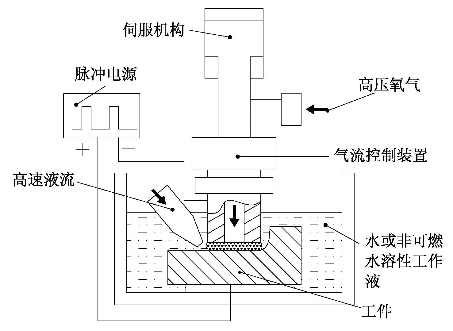
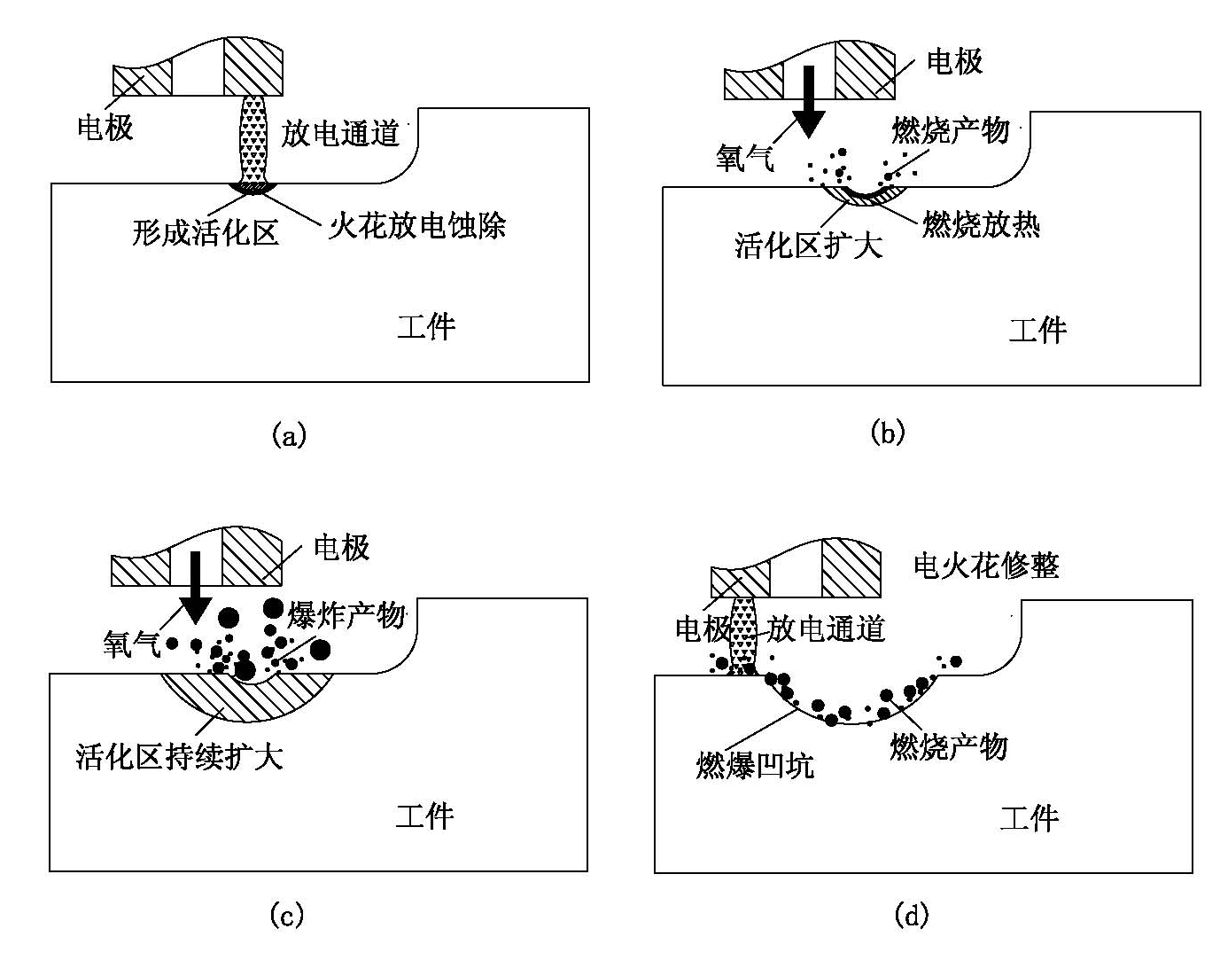
[0039] Such as figure 1 , 2 shown.

[0040] A kind of die steel Cr12 electric spark induces controllable combustion and electric discharge machining etch method, it comprises the following steps:

[0041] The first step is to build a processing system. Such as figure 1 As shown, the tubular electrode is connected to the airflow control device, the electrode can be rotated, and the high-pressure oxygen is transformed into intermittent adjustable intermittent oxygen flow under the action of the airflow control device. The electrode and Cr12 are respectively connected to the two poles of the pulse power supply to generate electric spark discharge. Water is used as the working medium. The liquid surface is more than 20mm away from the processing area to form a certain water pressure to strengthen the combustion effect. The water flow is used (the pressure depends on the gas pressure) ) to flush the processing area to speed up the discharge of erosion products.

[0042] The se...

example 2

[0052] An electric spark induced controllable combustion and electric discharge machining erosion method of superalloy GH4169, which differs from Example 1 in that the base material is different. The rest are the same as Example 1.

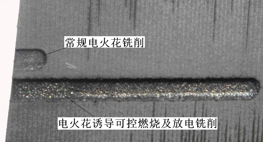
[0053] For an application example of high-temperature alloy GH4169 using EDM-induced controllable combustion milling and conventional EDM, as shown in Table 2, the physical photos of the processed workpiece corresponding to the same processing time are as follows image 3 shown.

[0054] Table 2 Comparison of GH4169 EDM-induced controllable combustion and EDM with conventional EDM methods

[0055]


PUM


Abstract

The invention relates to an electric spark induced controlled combustion and discharge machining corrosion removing method, and is characterized in that in the process of conventional electrical discharge machining (EDM), the gas which can generate combustion heat release effect with the metal materials to be machined is pumped into the machining area intermittently to ensure machining alternating between electric spark induced controlled combustion and conventional EDM; under the action of conventional EDM, the metal materials on the surface layer exceed the ignition point and form active state and generate combustion reaction with the pumped gas to generate the combustion products and simultaneously release plenty of heat; the heat directly acts on the metal base materials so that the metal base materials with volume duplicating that of the combusting materials are heated to molten state; and the combustion products and the molten metal materials are thrown off the matrix under the combined action of the heating and explosive power generated by electric spark discharge and flow scouring. The method has the advantages of high efficiency, low loss, low cost, safety and no pollution; and the problems of sizes, rigidity and the like of the machine tools of large structures can be solved simultaneously.

Description

technical field [0001] The invention relates to an electric spark machining method, in particular to an electric spark induced controllable combustion and electric discharge machining erosion method capable of improving the efficiency of electric spark machining, quickly eroding base metal materials and ensuring the quality and precision of the machined surface. Background technique [0002] With the advancement of science and technology and the development of industry, new materials emerge in an endless stream. These materials not only have high hardness, high strength, high wear resistance, but also have high melting point, strong corrosion resistance and other characteristics, making the processing difficulty of traditional cutting processing increasing day by day. Such as superalloys, because of their large work hardening tendency, high cutting force and high cutting temperature, the tool is easy to wear, and the surface quality and precision are not easy to guarantee. ...

Claims


Application Information

Patent Timeline
IPC IPC(8): B23H5/00
Inventor 刘志东田宗军王祥志邱明波汪炜沈理达黄因慧
Owner NANJING UNIV OF AERONAUTICS & ASTRONAUTICS
Learn More