Method for preparing thermal barrier coating

A technology of thermal barrier coating and ceramic coating, which is applied in the direction of coating, metal material coating process, ion implantation plating, etc., can solve the problem of insufficient resistance to thermal stress, high thermal conductivity of thermal barrier coating, and performance difference Large problems, to achieve the effect of small blockage, long life and excellent performance

Active Publication Date: 2011-10-12
BEIJING AERONAUTICAL MFG TECH RES INST
View PDF5 Cites 24 Cited by
  • Summary
  • Abstract
  • Description
  • Claims
  • Application Information

AI Technical Summary

Problems solved by technology

However, the layered structure of plasma spraying is parallel to the surface of the substrate, so that there are many transverse interfaces in the ceramic layer. The coating with this structure is not enough to resist the thermal stress generated by the thermal cycle in the high temperature working environment, which will cause the coating to peel off prematurely.
However, the coating prepared by EB-PVD can obtain a columnar crystal structure perpendicular to the surface of the substrate, which has a high stress tolerance, significantly improves the thermal stress resistance of the coating, and has a service life much longer than that of plasma sprayed thermal barrier coatings. layer, but the thermal barrier coating prepared by EB-PVD has higher thermal conductivity, and the thermal insulation effect is not as good as that of plasma sprayed thermal barrier coating
Although the composition of YSZ prepared by these two methods is the same, the performance is very different due to the different structure, so the structure is very important to the performance of YSZ coating

Method used


Image

  • Method for preparing thermal barrier coating
  • Method for preparing thermal barrier coating
  • Method for preparing thermal barrier coating

Examples


Embodiment Construction

[0026] The technical scheme of the present invention will be described in further detail below in conjunction with accompanying drawing and embodiment:

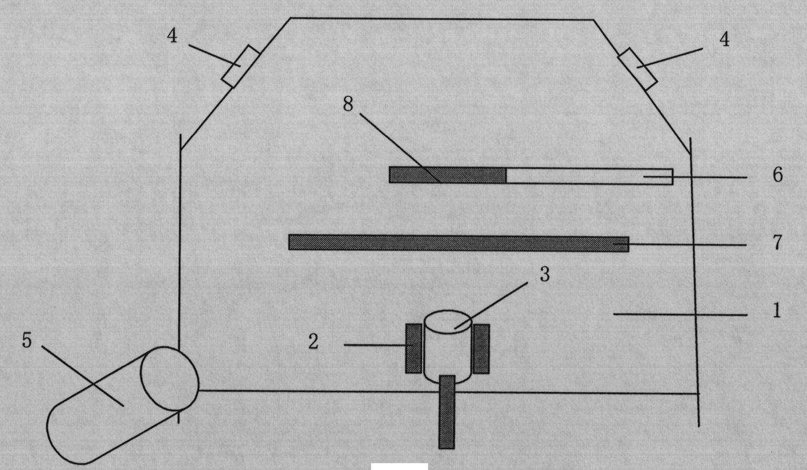
[0027] See attached figure 1 As shown, a kind of thermal barrier coating is prepared by adopting the technical scheme of the present invention, and its technological process is as follows:

[0028] (1) Put the NiCoCrAlY alloy bar stock 3 with a diameter of 70 mm and a length of 110 mm into the bar stock evaporation source crucible 2 of the vacuum chamber 1, and vacuum the vacuum chamber 1 to 1 × 10 -4 below pa;

[0029] The chemical composition and mass percentage of NiCoCrAlY alloy are: Co 20-23%, Cr 22-24%, Al 11-13%, Y 0.05-1.5%, and the balance is Ni;

[0030] (2) The workpiece 8 is moved directly above the alloy bar 3, and the baffle plate 7 is moved between the alloy bar 3 and the workpiece 8;

[0031] (3) pre-evaporate the alloy rod 3 with the electron gun 4, and adjust the electron beam current 1.6A;

[0032] (4) ...


PUM


Abstract

The invention discloses a method for preparing a thermal barrier coating. According to the method disclosed by the invention, a deposition matrix is bombarded by ion beams while a deposition coating is evaporated by electron beams, the steam energy of the electron beams is about 0.1-1 electron volts, and the energy is not enough to well migrate atoms in the process of depositing the coating; and the energy of the ion beams can reach thousands of electron volts, and the energy is enough to interfere growth of columnar crystals to increase crystal boundaries and crystal sub-boundaries and enlarge or increase microscopic holes so as to reduce phonon and photon scattering mean free path and reduce the thermal conductivity of the thermal barrier coating. The energy of vaporous clouds can be increased through activation ionization effects of ions; and compared with the conventional EB-PVD (Electron Beam Physical Vapour Deposition), the method can ensure that same performances can be achieved at low deposition temperature; furthermore, forms, structures and stresses of the columnar crystals can be also adjusted and controlled through ion assisted deposition, and thus, the service life ofthe thermal barrier coating can be prolonged.

Description

technical field [0001] The invention relates to a method for preparing a thermal barrier coating, which belongs to the technical field of surface treatment of metal materials. The thermal barrier coating with low thermal conductivity and long life can be prepared by using the method, and the invention is applicable to the fields of coating preparation and surface modification, including the preparation of metal and ceramic coatings. Background technique [0002] The currently widely used thermal barrier coating system for aero-engines is mainly composed of yttria partially stabilized zirconia (YSZ) ceramic coating and MCrAlY (where M stands for Ni, Co or NiCo) metal bonding layer, which plays a role of thermal insulation What is YSZ ceramic coating. The structure and performance of YSZ coating are closely related to the preparation method and process parameters. The preparation methods are mainly plasma spraying and electron beam physical vapor deposition (EB-PVD). Both met...

Claims


Application Information

Patent Timeline
Patent Type & Authority Applications(China)
IPC IPC(8): C23C14/30C23C14/14C23C14/08
CPCY02T50/60
Inventor 高巍巩水利张华芳武洪臣刘亮雷新更彭丽平
Owner BEIJING AERONAUTICAL MFG TECH RES INST
Why Eureka
Try Eureka