

Composite photoelectric catalyst as well as preparation and applications
A catalyst and photoelectric technology, applied in the field of composite photocatalysts, can solve the problems of low solar energy utilization rate, high recombination rate, and low photocatalytic efficiency, and achieve the effects of improving photocatalytic efficiency, low cost, and simple preparation method
- Summary
- Abstract
- Description
- Claims
- Application Information
AI Technical Summary
Problems solved by technology
Method used
Image

Examples
Embodiment 1
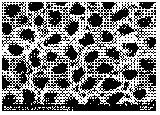
[0024] (1) Preparation of titania nanotube arrays
[0025] ① Grind the surface of the base material titanium sheet, clean it and set aside;
[0026] ② Preparation of inorganic electrolyte: the electrolyte is composed of 0.1M NaF and 0.5M NaHSO 4 The composition of the aqueous solution;
[0027] ③Under the condition of 15V DC voltage, using pure titanium sheet as the anode and platinum sheet as the cathode, the titanium dioxide nanotube array is electrolyzed in the electrolyte;
[0028] ④The titania nanotube array prepared above was calcined under aerobic conditions at 500°C for 3 hours to crystallize it into a titania nanotube array. see figure 1 .
[0029] (2) Preparation of graphene (RGO) film:
[0030] ① Preparation of graphene oxide aqueous dispersion: graphene oxide dispersed Na 2 HPO 4 -KH 2 PO 4 In the buffer solution, sonicate for 30 minutes and set aside;
[0031] ②Using the titanium dioxide nanotube array electrode as the working electrode, the platinum ele...
Embodiment 2
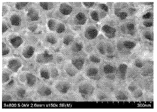
[0041] (1)CuInS 2 / RGO-TiO 2 Fabrication of Composite Nanotube Arrays
[0042] The RGO-TiO prepared in Example 1 2 Nanotube array in 20ml containing CuCl 2 (2mmol), InCl 3 (2mmol) and Na 2 S 2 o 3 (20mmol) solution, in standard three-electrode system, in TiO 2 Electrodeposition of CuInS on the nanotube array (relative to the saturated calomel electrode, the energization voltage is -2.5V, the pulse time on-off ratio is 0.5 seconds: 1 second) 2 / RGO-TiO 2 Composite nanotube arrays. see Figure 4 .
[0043] (2)CuInS 2 / RGO-TiO 2 Photocatalytic degradation of methylene blue and 2,4-dichlorophenoxyacetic acid by composite materials
[0044] CdS / RGO-TiO in embodiment 1 2 Replaced by CuInS 2 / RGO-TiO 2 , the rest are the same as in Example 1, the degradation efficiency of methylene blue is 98%, and the degradation efficiency of 2,4-dichlorophenoxyacetic acid is 97%.
Embodiment 3
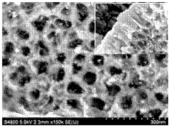
[0046] (1) WO 3 / RGO-TiO 2 Fabrication of Composite Nanotube Arrays
[0047] At 30°C, slowly add 1g of tungsten powder into 20mL of 30% H 2 o 2 , stirred for 2 hours, the black tungsten powder was almost completely covered by H 2 o 2 Oxidative dissolution, only a small amount of white precipitate of insoluble oxides of W, and clear peroxytungstic acid sol was obtained after sol filtration. Add 20 mL of absolute ethanol to the sol to consume unreacted H 2 o 2 And makes the sol band negatively charged. The RGO-TiO prepared in Example 1 2 The nanotube array was immersed in the above sol for 2 hours, and then aerobically calcined at 400°C for 5 hours to obtain WO 3 / RGO-TiO 2 Composite nanotube arrays. see Figure 5 .
[0048] (2) WO 3 / RGO-TiO 2 Photocatalytic degradation of methylene blue and 2,4-dichlorophenoxyacetic acid by composite materials
[0049] CdS / RGO-TiO in embodiment 1 2 replace with WO 3 / RGO-TiO 2 , the rest are the same as in Example 1, the deg...
PUM
 Abstract
Description
Claims
Application Information