Modified fly ash, preparation method thereof, and preparation apparatus thereof

A technology of fly ash and ultra-fine fly ash, which is applied in the treatment of dyed organic silicon compounds, dyed low-molecular organic compounds, and fibrous fillers. It can solve the problem of non-spherical particles, uneven particle surface distribution, and large dosage. To meet the coupling and filling effect, improve the economic value, and achieve the effect of large production volume

Inactive Publication Date: 2012-10-17
EAST CHINA NORMAL UNIV
View PDF8 Cites 23 Cited by
  • Summary
  • Abstract
  • Description
  • Claims
  • Application Information

AI Technical Summary

Problems solved by technology

The defect of the prior art is that the modifier is directly added in the production of rubber and plastic products, the dosage is large, the distribution on the surface of the particles is uneven, the energy consumption of the grinding process is high, the particles are not spherical and have sharp edges, and the residual amount of iron oxide is large , and poor sealing of the production process or processing equipment causes fine particles to fly into the atmosphere, etc., which affects the filling effect and the appearance and quality of the product, such as frosting on the rubber surface, decline in mechanical strength, etc., and seriously restricts the modification of pulverized coal. Large-scale production of ash and popularization and use in rubber and plastic industry
As disclosed in the patent CN 1156334C, the method and equipment for segmental extraction of fly ash micro- and nano-sized particles have not yet solved the problem of surface modification of fly ash particles, and still affect the effect of directly adding and using it in rubber and plastics

Method used


Image

  • Modified fly ash, preparation method thereof, and preparation apparatus thereof
  • Modified fly ash, preparation method thereof, and preparation apparatus thereof

Examples


Embodiment 1

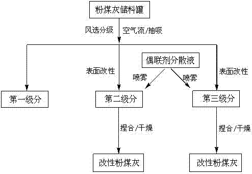
[0034] Such as figure 1 As shown, the fly ash in the fly ash storage tank is sent into the gas-material mixer with compressed air, and under the suction of the induced draft fan, the fly ash particles are introduced into the cyclone air flow separator through the pipeline along with the air flow , Air separation and grading are carried out in the negative pressure system of the closed equipment. The cyclone airflow separator includes a first-stage separator, a second-stage separator, and a third-stage separator.

[0035] Switch the air flow and control the small suction force of the fan, so that the coarse particles spiral down in the first stage sorter, and are discharged through the discharge port and stored in the container (accounting for about 15% of the weight of the original ash). The coarse particles are fractions rich in magnetic iron oxide, which can be directly used as magnetic fillers, or further obtained through magnetic separation to obtain high-grade magnet raw...

Embodiment 2

[0040] refer to figure 1 , the fly ash in the storage tank is sent into the gas-material mixer with compressed air, and under the suction of the induced draft fan, it is introduced into the cyclone air flow separator through the pipeline along with the air flow, and the suction force of the fan at this stage is adjusted. In Example 1, the corresponding wind force is slightly stronger, and the coarse particles spirally descend in the first stage sorter, and are discharged through the discharge port and stored in the container (accounting for about 30% of the weight of the original ash).

[0041] With reference to Example 1, further, by switching the swirl flow and maintaining the suction force of the fan at this stage is basically the same as the corresponding wind force in Example 1, subdividing in the second stage sorter to obtain ultrafine particles above 1200 mesh . Ultrafine particles above 1,200 mesh enter the second-stage sorter and descend spirally (accounting for abou...

Embodiment 3

[0045] The fly ash in the storage tank is sent into the gas-material mixer with compressed air, and under the suction of the induced draft fan, it is introduced into the cyclone air flow separator through the pipeline along with the air flow, and the suction force of the fan at this stage is controlled more effectively. In Example 2, the corresponding wind force is stronger, and the coarse particles spiral down in the first stage sorter, and are discharged through the discharge port and stored in the container (accounting for about 50% of the original ash weight).

[0046] With reference to Example 1, further, by switching the swirling flow and maintaining the process conditions that the suction force of the fan at this stage is basically the same as the corresponding wind force in Example 1, subdivide in the second stage separator to obtain more than 2000 mesh ultrafine particles. Ultra-fine particles above 2000 mesh enter the second-stage sorter and descend spirally (account...


PUM

PropertyMeasurementUnit
particle size (mesh)aaaaaaaaaa

Abstract

The invention provides a preparation method of modified fly ash. In a sealed negative-pressure system, fly ash is adopted as a raw material. When winnowing grading processing is carried out upon the fly ash particles, the graded fine particles and ultra-fine particles are subjected to a chemical-spraying surface modification treatment; the obtained products are heated and dried, such that a target product of the modified fly ash is obtained. According to the modified fly ash provided by the invention, one or more saturated-structure or unsaturated-structure organic groups are bonded on the surfaces of the particles, and an activation index is higher than 0.9. The invention also discloses a fly ash sorting and modifying apparatus. The technical method provided by the invention is energy-saving and environment-friendly, and is advantaged in high utilization rate of fly ash. The obtained modified fly ash is advantaged in wide particle fineness selection range, small dosage of a coupling agent, uniform distribution of the coupling agent, good adaptability with polymer substrates, and the like. In rubber product filling, the modified fly ash can be used for completely replacing calcium carbonate and powdered steatile, or partially replacing carbon black. The modified fly ash is a renewable resource material with low cost and high quality.

Description

technical field [0001] The invention relates to the technical field of filler processing for rubber products, in particular to a method for preparing modified fly ash, its classification and surface treatment, and a device for realizing it. Background technique [0002] Fly ash is a solid waste discharged from coal-fired thermal power plants. It is a dispersed system composed of particles of different structures and shapes. The main chemical components of fly ash are silicon, aluminum, iron oxides, a certain amount of calcium, magnesium, sulfur oxides, traces of copper, chromium, lead, etc., and unburned carbon particles. The total annual discharge of fly ash in the country has exceeded 100 million tons, and less than 50% of it has been utilized. A large amount of fly ash is accumulated in the ash yard, which not only occupies land resources, but also pollutes water quality and the environment. Untreated fly ash can only be used as raw materials for building materials, such...

Claims


Application Information

Patent Timeline
Patent Type & Authority Applications(China)
IPC IPC(8): C09C1/00C09C3/04C09C3/08C09C3/12C08L23/28C08L7/00C08K13/06C08K9/04C08K9/06
Inventor 谢美然张以群王国伟郑昌武
Owner EAST CHINA NORMAL UNIV
Why Eureka
Try Eureka