Pressure sensor encapsulation structure containing silicon through holes

A technology of pressure sensor and packaging structure, which is applied in the direction of microstructure technology, measuring fluid pressure, microstructure device, etc., can solve the problems of expensive welding equipment, difficult production, and affecting the accuracy of pressure measurement, so as to reduce the packaging volume and weight, The effect of increasing test sensitivity and realizing local airtightness

Inactive Publication Date: 2012-10-24
PEKING UNIV
View PDF6 Cites 19 Cited by
  • Summary
  • Abstract
  • Description
  • Claims
  • Application Information

AI Technical Summary

Problems solved by technology

This type of packaging structure has certain limitations: 1. The process cost is high and the welding equipment is expensive; 2. The packaging volume is large, which is not conducive to the lightness, thinning and miniaturization of the product; 3. The thermal expansion coefficient mismatch between the silicone oil and the chip is easy Affect the pressure measurement accuracy; 4. The non-airtightness in the sealing is easy to cause oil leakage, oil leakage, and damage the pressure sensor; 5. The filling of silicone oil will more or less introduce part of the pressure error; 6. Metal wire bonding Wires and solder joints are susceptible to fatigue failure in high-shock, high-speed pressure cycle environments
This packaging solution does not need to be filled with silicone oil, can ensure airtight packaging, and is suitable for a variety of applications. As long as the environment has no effect on silicon or glass materials, this type of packaging structure can even be used for ultra-small pressure sensors such as conductive fluids; but this type Packaging needs to use special materials and special processes, which is costly and difficult to manufacture

Method used


Image

  • Pressure sensor encapsulation structure containing silicon through holes
  • Pressure sensor encapsulation structure containing silicon through holes
  • Pressure sensor encapsulation structure containing silicon through holes

Examples


Embodiment 1

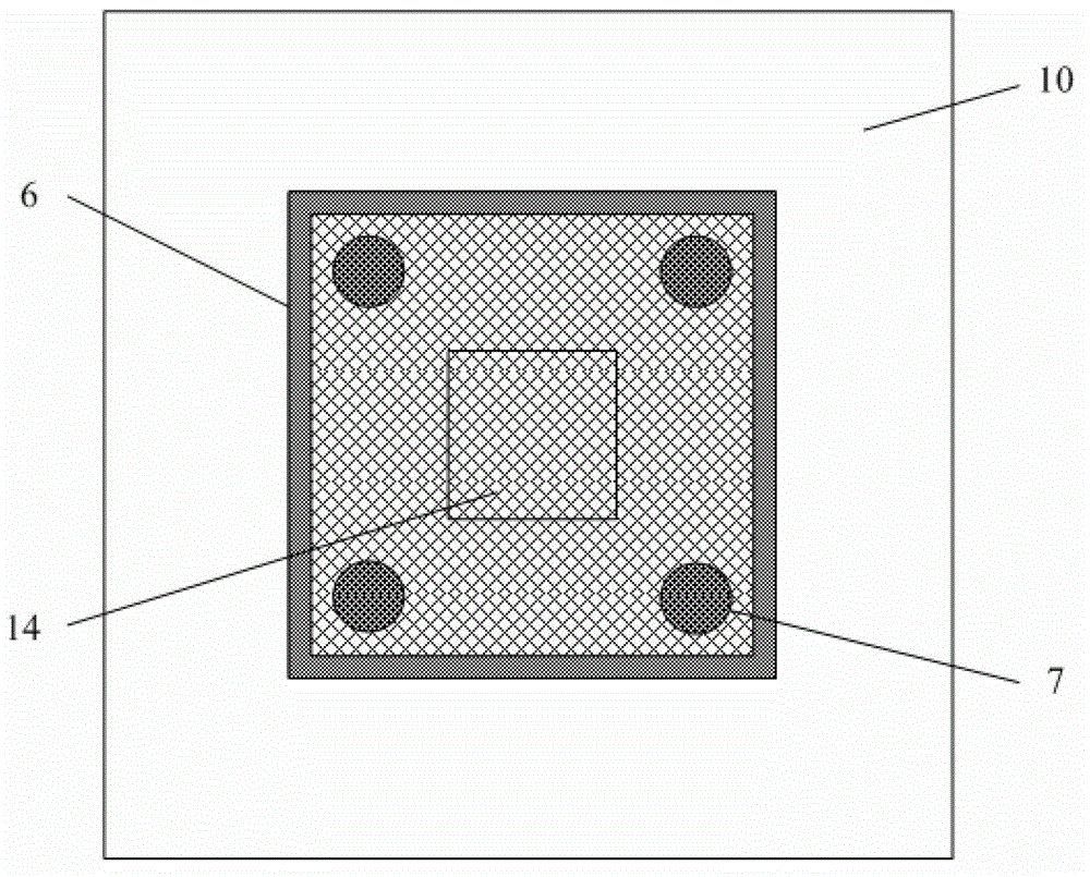
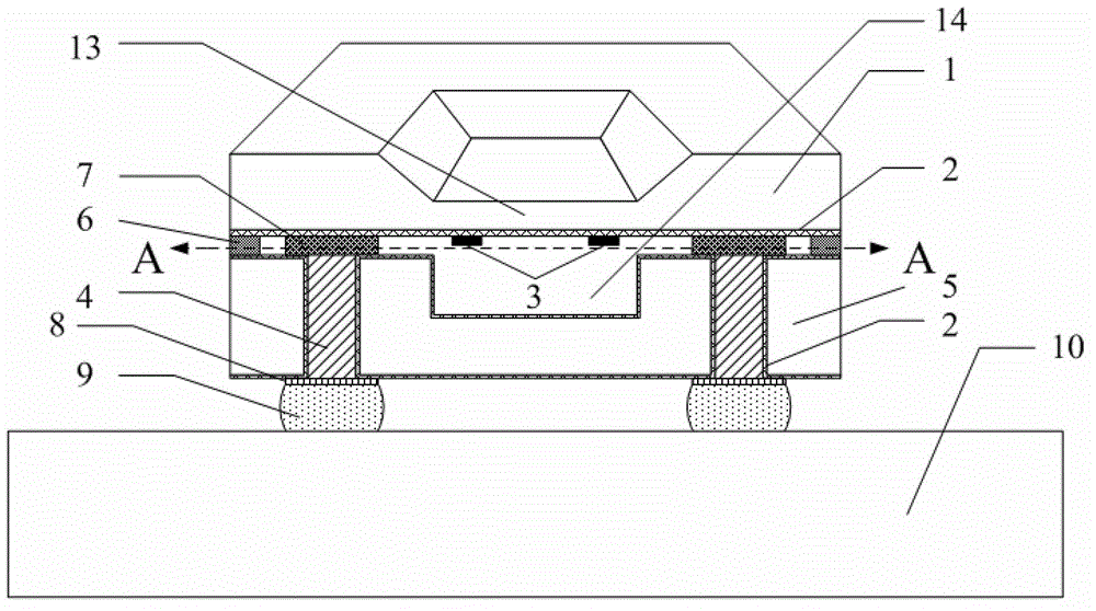
[0033] like image 3 As shown, the present invention uses the DRIE process to etch blind silicon vias with a depth of about 100-200 μm on the silicon base 5 from the back to the front at the position corresponding to the data signal port of the SOI pressure sensor chip 1 (wherein the DRIE process parameters are: SF 6 Gas flow 130sccm, C 4 F 8 The gas flow rate is 100sccm, the stage power is 600W, the automatic pressure control APC is selected as 60, the passivation is 7s after every 9s of etching, and the etching rate is about 2μm / min (the specific parameters are closely related to the etching area)); the thermal oxygen forms a thickness of 2μm SiO 2 Insulating sidewalls or depositing SiNx, magnetron sputtering deposition adhesive layer The barrier layer W forms an insulating barrier layer 2, and at the same time sputters a 1-2 μm seed layer on the sidewall of the blind hole, wherein the material of the seed layer is the same as the conductive material filled in the sili...

Embodiment 2

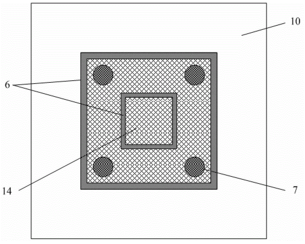
[0035] like Figure 4 As shown, the second embodiment of the present invention is similar to the first embodiment, the main difference is that the front side of the silicon base 5 is thinned and polished by CMP, and after the through hole 4 is formed through the substrate, electroplating or chemical plating is performed at the position of the through hole 4 to form conductive micro-convex. At point 7, a ring-shaped bonded metal ring structure is electroplated or electrolessly plated on both sides of the inner and outer periphery at the same time, wherein the material of the bonded metal ring 6 is an airtight material. The remaining process steps are the same and will not be repeated here. The silicon piezoresistive strips 3 are distributed at a horizontal distance of 100-200 μm from the edge of the silicon film 13 close to the pressure sensor, and are placed in the concave groove 14 of the silicon base 5 after packaging.

Embodiment 3

[0037] like Figure 5 As shown, the third embodiment of the present invention is as follows:

[0038] The process steps of flip-chip bonding the pressure sensor chip 1 on the silicon base 5 are as follows: the silicon base 5 is etched with a depth of about 100-200 μm from the back to the front at the position corresponding to the data signal port of the SOI pressure sensor chip 1 using a DRIE process. Silicon blind vias followed by deposition of 2 μm thick SiO 2 or SiNx insulating layer, adhesive layer The barrier layer W forms an insulating barrier layer 2, and sputters a 1-2 μm seed layer at the same time, wherein the material of the seed layer is the same as the conductive material filled with the silicon blind hole; the silicon blind hole is electroplated to form a conductive column, and the UBM8 structure is prepared by electroplating or electroless plating process. , and then etch to remove the surface adhesion layer Ti / barrier layer W / seed layer; the back side of t...


PUM

PropertyMeasurementUnit
thicknessaaaaaaaaaa

Abstract

The invention provides a pressure sensor encapsulation structure containing silicon through holes, which uses a silicon base to substitute a traditional boron-phosphorosilicate glass base, and adopts a flip chip bonding technology and a bonding technology (such as CuSn bonding, AuSn eutectic bonding, Cu-Cu bonding and Au-Au bonding) to realize the airtight vacuum encapsulation of pressure sensors; a monocycle or bi-cycle bonding metal ring is adopted for encapsulation, and plays the role of reducing the bonding stress on the encapsulation of the pressure sensors with different piezoresistance strip distribution under the condition of ensuring the measurement sensitivity; and conductive columns are adopted for replacing metal wires to be used as signal lead wires, so the mutual connection reliability is increased. Compared with encapsulation structures of the silicon glass electrostatic bonding technology, the metal wire bonding technology, the metal isolating membrane technology and the airtight cavity silicone oil filling technology which are adopted traditionally, the pressure sensor encapsulation structure cancelled silicone oil filling and the metal isolating membrane, contributes to the improvement in the pressure sensor sensitivity, can also be used for dynamic pressure detection, and has the advantages of small size and high integration level.

Description

technical field [0001] The invention relates to a pressure sensor package structure containing through-silicon holes, belonging to the technical field of microelectronics. Background technique [0002] At present, pressure sensors are widely used in the consumer electronics industry, automotive electronics industry, petrochemical sector, aerospace sector and other fields. The failure and failure of pressure sensors are mostly caused by packaging failures, and packaging has become a key technology for pressure sensor applications. Pressure sensor vacuum packaging often adopts metal tube shell, metal isolation diaphragm, metal base, filling with silicone oil, wire bonding technology, and uses welding technology to weld metal tube shell, metal isolation diaphragm and metal tube base to form a closed cavity; Electrostatic bonding or gold-silicon eutectic bonding technology, the pressure sensor is sealed on the metal tube seat through borophosphosilicate glass; and the sealed cav...

Claims


Application Information

Patent Timeline
Patent Type & Authority Applications(China)
IPC IPC(8): G01L19/14B81B7/00
Inventor 刘振华陈兢金玉丰
Owner PEKING UNIV
Why Eureka
Try Eureka