Hydrogen-production and on-line separation device for decomposing water by optical electrolytic cell
A separation device and a technology for producing hydrogen from water, which is applied in the electrolysis process, electrolysis components, light water/sewage treatment, etc., can solve the problems of less optimal design of the photoelectrolytic cell structure and no semiconductor materials, and achieve the elimination of post-processing steps, Effective use of the illuminated area and the effect of avoiding corrosion
- Summary
- Abstract
- Description
- Claims
- Application Information
AI Technical Summary
Problems solved by technology
Method used
Image

Examples
specific Embodiment approach
[0050] Its specific implementation is as follows:
[0051] 1) Titanium dioxide nanotube photoanode integrated with titanium dioxide and substrate was prepared by pure titanium mesh.
[0052] The pure titanium mesh is used as the anode, the graphite electrode or the Pt sheet electrode is used as the cathode, placed in the reactor, and a certain distance (4cm) is kept between the two electrodes, and the electrolyte solution contains NH 4 The ethylene glycol (89.5wt%) water (10wt%) solution of F (0.5wt%), copper wire is done lead wire and two electrodes are connected on the two poles of DC stabilized voltage power supply, start reaction, and regulating voltage is 30V. After reacting for 4 h, the reaction was terminated. The prepared titanium mesh was baked in a muffle furnace at 450° C. for 120 minutes, and the titanium dioxide nanotube photoanode was obtained after natural cooling.
[0053] 2) Pressing of the membrane electrode assembly.
[0054] Take commercial Pt / C carbon p...
Embodiment 2
[0065] Its specific implementation is as follows:
[0066] 1) Titanium dioxide nanotube photoanode integrated with titanium dioxide and substrate was prepared by pure titanium mesh.
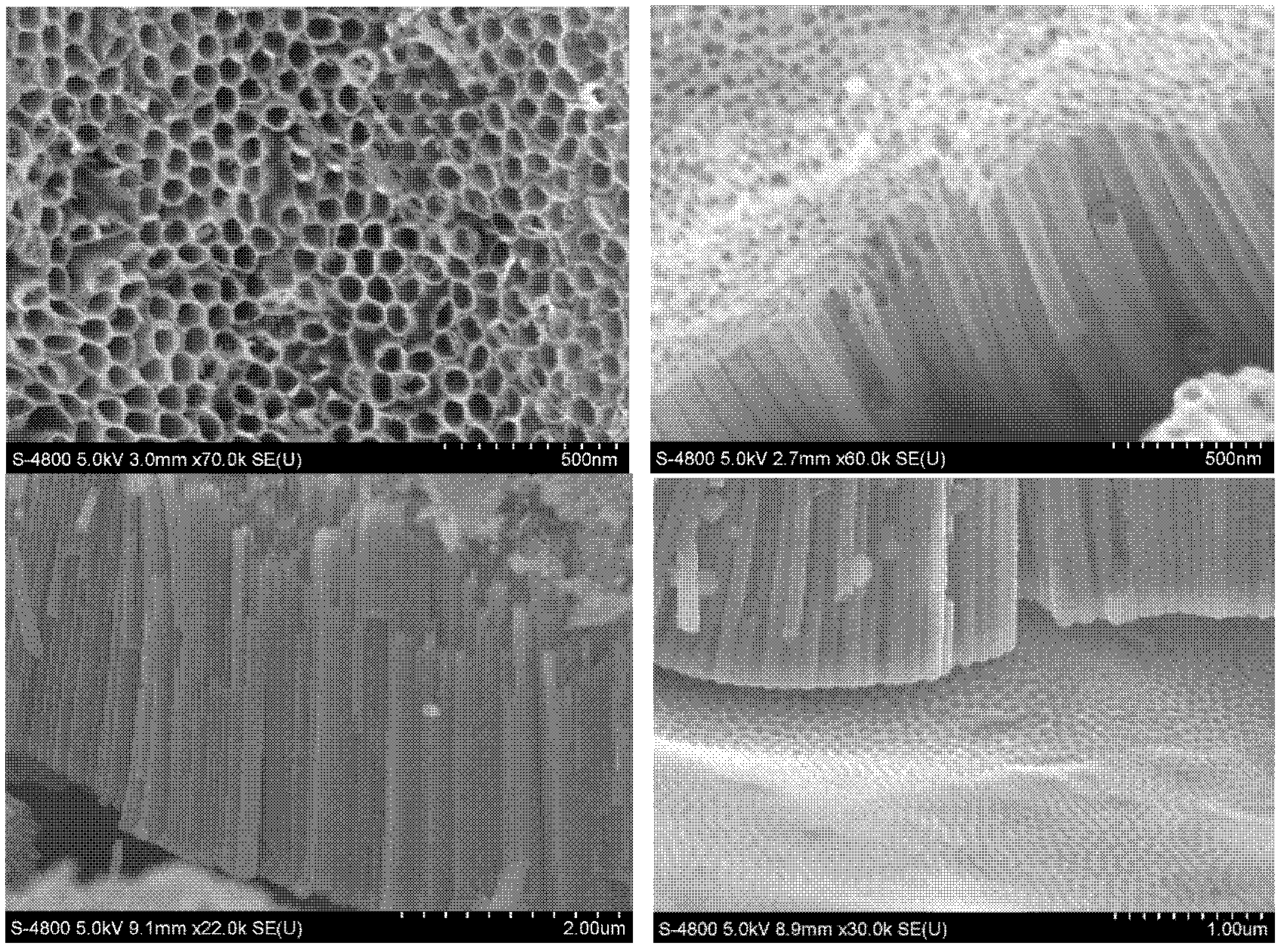
[0067] The pure titanium mesh is used as the anode, the graphite electrode or the Pt sheet electrode is used as the cathode, placed in the reactor, and a certain distance (4cm) is kept between the two electrodes, and the electrolyte solution contains NH 4 The ethylene glycol aqueous solution of F, the copper wire is used as the wire to connect the two electrodes to the DC regulated power supply, and the reaction starts, and the voltage is adjusted to 30V. After reacting for 1 h, the reaction was terminated. The prepared titanium mesh is placed in a muffle furnace for calcination, 120min at 650°C, and after natural cooling, the titanium dioxide nanotube photoanode can be obtained, and the calcined TiO 2 The surface morphology of the nanoarrays is as Figure 9 shown.
[0068] 2) Pressing of the...
Embodiment 3
[0074] Its specific implementation is as follows:
[0075] 1) Titanium dioxide nanotube photoanode integrated with titanium dioxide and substrate was prepared by pure titanium mesh.
[0076] The pure titanium mesh is used as the anode, the graphite electrode or the Pt sheet electrode is used as the cathode, placed in the reactor, and a certain distance is kept between the two electrodes, and the electrolyte solution contains NH 4 The ethylene glycol (89.5wt%) water (10wt%) solution of F (0.5wt%), copper wire is done lead wire and two electrodes are connected on the direct-current stabilized voltage power supply, starts to react, and regulation voltage is 30V. After reacting for 1 h, the reaction was terminated. The prepared titanium mesh was baked in a muffle furnace at 450° C. for 120 minutes, and the titanium dioxide nanotube photoanode was obtained after natural cooling.
[0077] 2) Pressing of the membrane electrode assembly.
[0078] Take commercial Pt / C carbon paper e...
PUM
 Abstract
Description
Claims
Application Information
 - R&D
- Intellectual Property
- Life Sciences
- Materials
- Tech Scout
- Unparalleled Data Quality
- Higher Quality Content
- 60% Fewer Hallucinations
Browse by: Latest US Patents, China's latest patents, Technical Efficacy Thesaurus, Application Domain, Technology Topic, Popular Technical Reports.
© 2025 PatSnap. All rights reserved.Legal|Privacy policy|Modern Slavery Act Transparency Statement|Sitemap|About US| Contact US: help@patsnap.com