Industrial furnace comprehensive energy saving and emission reduction integrated system

An energy-saving emission reduction and integrated system technology, applied in the direction of indirect carbon dioxide emission reduction, furnaces, furnace components, etc., can solve problems such as increased power consumption of kiln tail fans, failure to meet emission standards, and unsuitability for industrial kilns, etc., to achieve increased Power consumption and operation and maintenance costs, scale reduction, and the effect of reducing equipment footprint

Inactive Publication Date: 2013-06-26
DALIAN EAST NEW ENERGY DEV
View PDF6 Cites 5 Cited by
  • Summary
  • Abstract
  • Description
  • Claims
  • Application Information

AI Technical Summary

Problems solved by technology

The most widely used flue gas denitrification technologies are SCR technology and SNCR technology. The denitrification efficiency of SCR technology can reach more than 95%. However, due to the large investment, complex system, and high operating costs, it is not suitable for industrial furnaces.
Although SNCR denitrification technology has low investment, low operating cost, simple system and wide application range, its denitrification efficiency is very low and cannot meet the national emission standards.
At present, there are patents combining SCR and SNCR denitrification technologies for denitrification. In this technology, SCR denitrification technology still has some disadvantages, because it is applied to the denitrification of industrial kiln flue gas, and the flue gas contains alkaline substances, which will cause catalyst poisoning and reduce reaction efficiency. , the catalyst needs to be replaced frequently, and the price of the catalyst is very high, which greatly increases the operating cost
In addition, there are many trays distributed inside the SCR reaction tower, and the trays are covered with catalysts, resulting in increased flue gas resistance and increased power consumption of the kiln tail fan.
This technology is not suitable for comprehensive energy saving and emission reduction of industrial kilns

Method used


Image

  • Industrial furnace comprehensive energy saving and emission reduction integrated system
  • Industrial furnace comprehensive energy saving and emission reduction integrated system
  • Industrial furnace comprehensive energy saving and emission reduction integrated system

Examples


Embodiment Construction

[0022] Below in conjunction with accompanying drawing and embodiment the present invention is described in further detail:

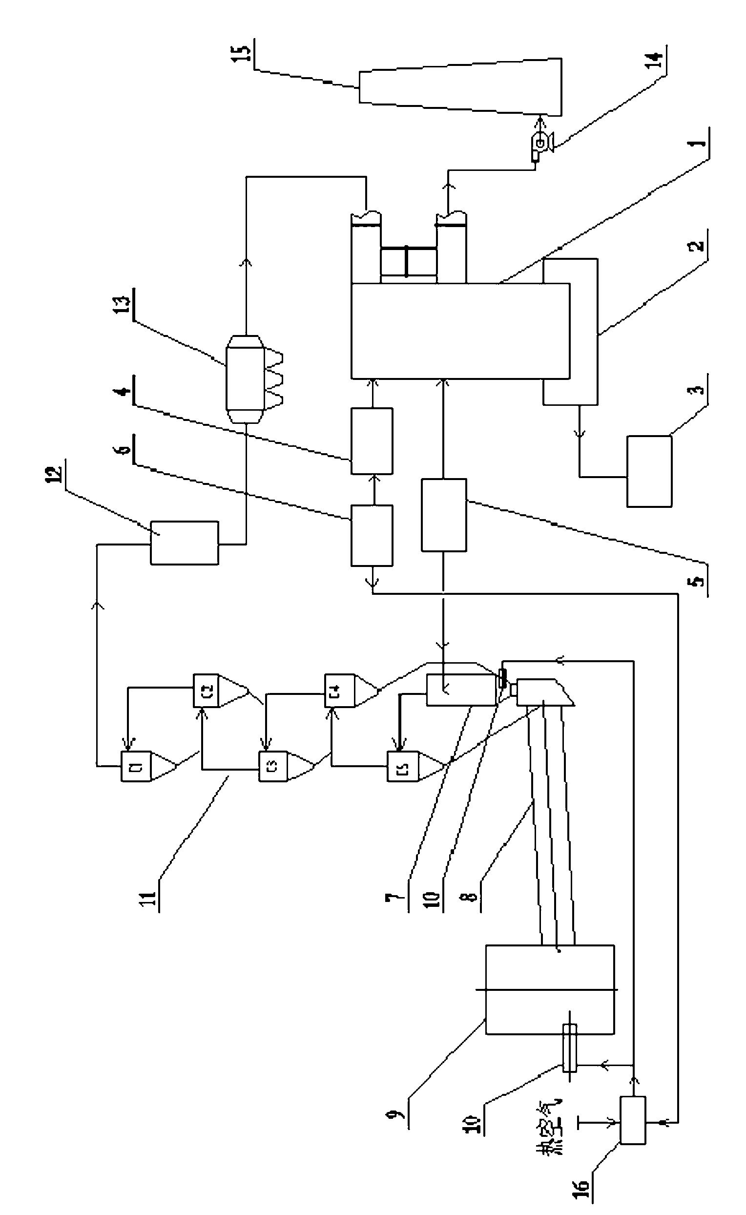
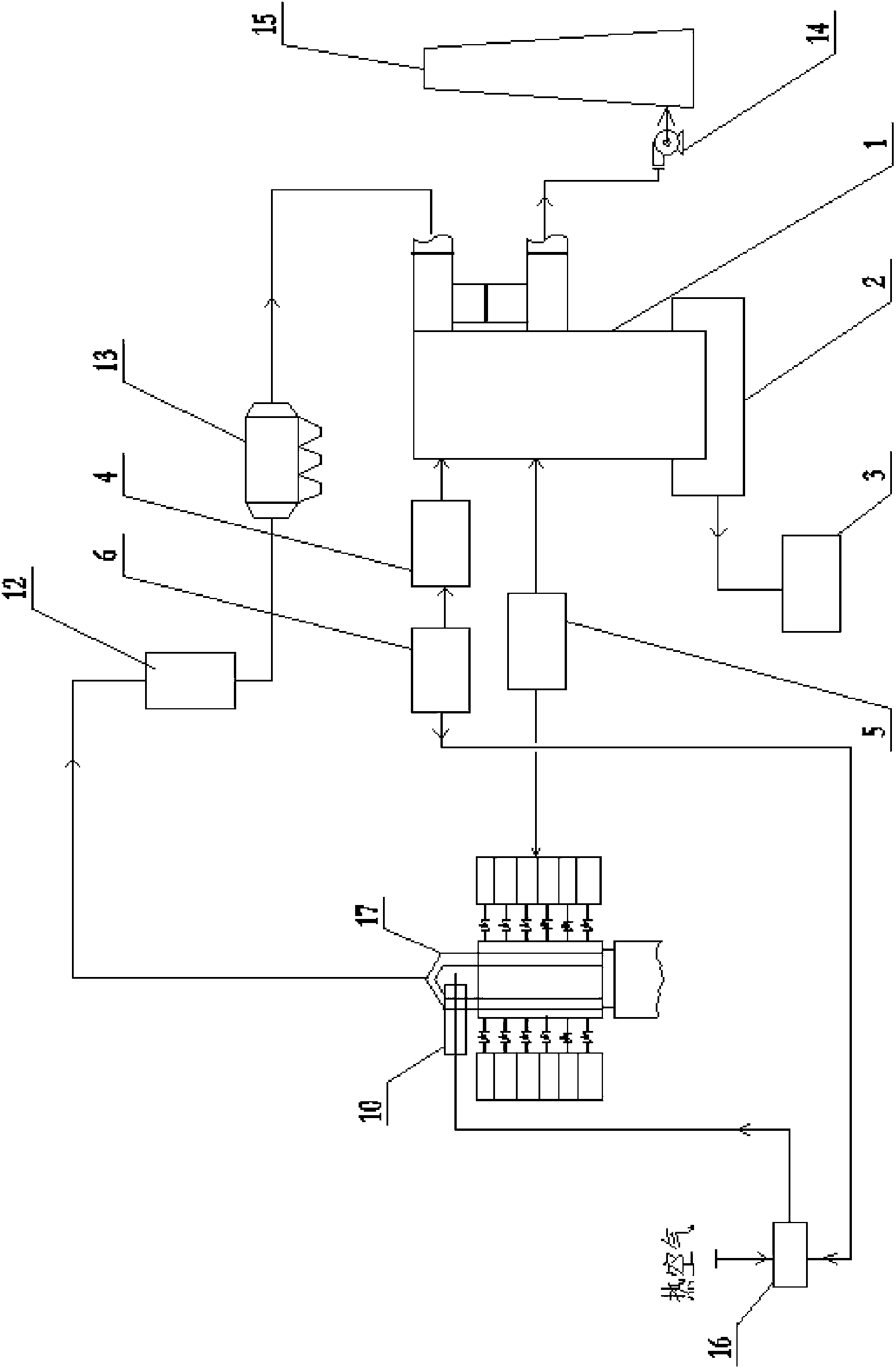
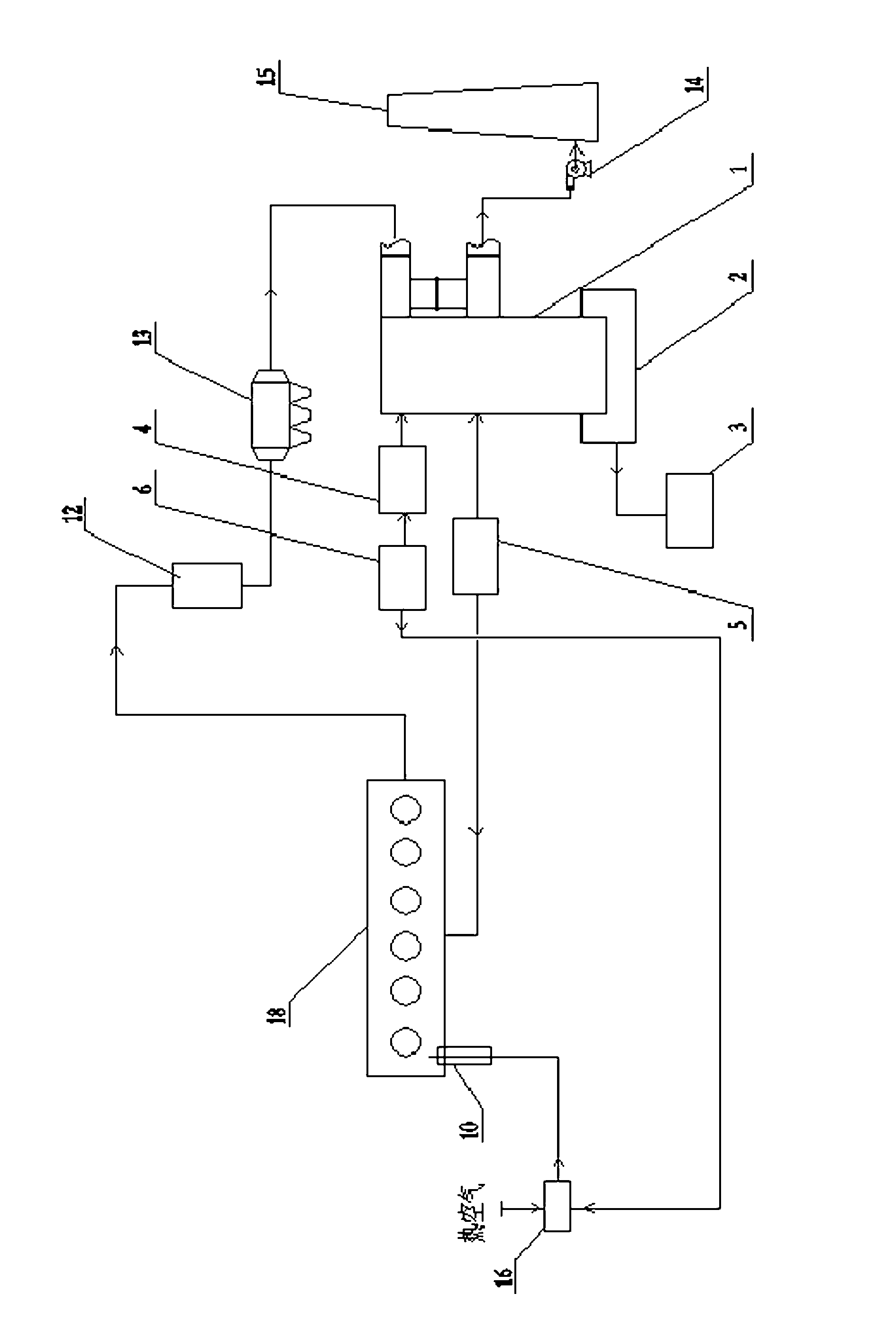
[0023] exist figure 1 In the schematic flow chart of the cement kiln comprehensive energy saving and emission reduction system shown, the cement kiln head is equipped with a burner at the front of the cement rotary kiln body, and the calciner is equipped with a burner at the kiln tail. The decomposition furnace is connected with the heat medium inlet of the cement raw meal preheater. The preheater is connected in series in multiple stages. The flue gas outlet of the last stage preheater is connected with the inlet of the dust collector. A waste heat boiler is set between the two. The outlet of the dust collector is connected to the inlet of the oxidation neutralization and denitration reaction tower, the outlet of the oxidation neutralization and denitration reaction tower is connected to the chimney, and an induced draft fan is arranged between the two...


PUM


Abstract

An industrial furnace comprehensive energy saving and emission reduction integrated system is characterized in that the industrial furnace comprehensive energy saving and emission reduction integrated system is a comprehensive integration integrated system which compounds oxygen-enriched combustion-supporting technology, a selective non-catalytic reduction (SNCR) denitrification method and an oxidation neutralization desulfurization and denitrification dedusting method. The industrial furnace comprehensive energy saving and emission reduction integrated system comprises a waste heat boiler, a deduster, a reducing agent spray atomization device, an oxidation neutralization denitrification reaction tower, an ammonium salt pond, an oxygen-enriched generating device, a wind mixing device, an ozone generating device and an ammonium salt liquid-solid separation device, wherein the waste heat boiler, the deduster, the reducing agent spray atomization device, the oxidation neutralization denitrification reaction tower, the ammonium salt pond, the oxygen-enriched generating device, the wind mixing device, the ozone generating device and the ammonium salt liquid-solid separation device are sequentially connected. The industrial furnace comprehensive energy saving and emission reduction integrated system not only is reasonable in process route and high in desulfurization and denitrification efficiency and combustion efficiency; but also is high in use rates of desulfurization and denitrification absorbent, can effectively reduce consumption of fuel such as fire coal, and improves yield of a furnace. Besides, clinker combusted quality of a cement kiln in an industrial furnace can be effectively improved, and intensity of cement end products can be improved by 3 to 28 days.

Description

technical field [0001] The invention relates to a comprehensive energy-saving and emission-reducing device for oxygen-enriched combustion and flue gas desulfurization and denitrification for an industrial kiln. Background technique [0002] The firing system of industrial kilns is the central link in the production process of building materials, and it is also a process that consumes a lot of fuel. Therefore, energy saving is the most prominent issue in the firing system of industrial kilns. Oxygen-enriched combustion technology, especially local oxygen-increased combustion-supporting technology, has been successfully applied in thermal power, petroleum, chemical and other industries, but it has not been applied in the building materials industry. According to the application of other industries, the local oxygen-increasing combustion technology can not only save energy obviously, but also reduce the emission of CO, CO2, SOx, NOx and soot, but it still cannot meet the requir...

Claims


Application Information

Patent Timeline
Patent Type & Authority Applications(China)
IPC IPC(8): F27D17/00F23L7/00B01D53/79B01D53/60
CPCY02E20/34
Inventor 金万金唐金泉滕小平孙明朗
Owner DALIAN EAST NEW ENERGY DEV
Why Eureka
Try Eureka