Method for preparing high-purity monocrystalline silicon through electrolytic refining-liquid cathode in-situ directional solidification

A technology of electrolytic refining and liquid cathode, which is applied in the direction of single crystal growth, single crystal growth, chemical instruments and methods, etc., can solve the problems of long process routes, achieve the effects of reducing environmental hazards, reducing manufacturing costs, and improving resource utilization

Active Publication Date: 2013-08-14
UNIV OF SCI & TECH BEIJING
View PDF7 Cites 9 Cited by
  • Summary
  • Abstract
  • Description
  • Claims
  • Application Information

AI Technical Summary

Problems solved by technology

However, because this process uses other metals with a lower melting point as the cathode, the silicon deposited on the cathode is stil

Method used


Image

  • Method for preparing high-purity monocrystalline silicon through electrolytic refining-liquid cathode in-situ directional solidification

Examples


Embodiment 1

[0026] Step 1. Melting of the anode silicon-containing alloy: use Cu, which is denser than silicon and more electronegative than silicon, and metallurgical grade silicon is mixed in a ratio of 1:3, and used as the anode after melting;

[0027] Step 2. Melting of the electrolyte: the electrolyte system uses BaF 2 with SiO 2 The mixture, melted as electrolyte system, standby; among them, SiO 2 The content is 1wt%;

[0028] Step 3. The initial raw material of the cathode is liquid high-purity silicon with a purity above 6N;

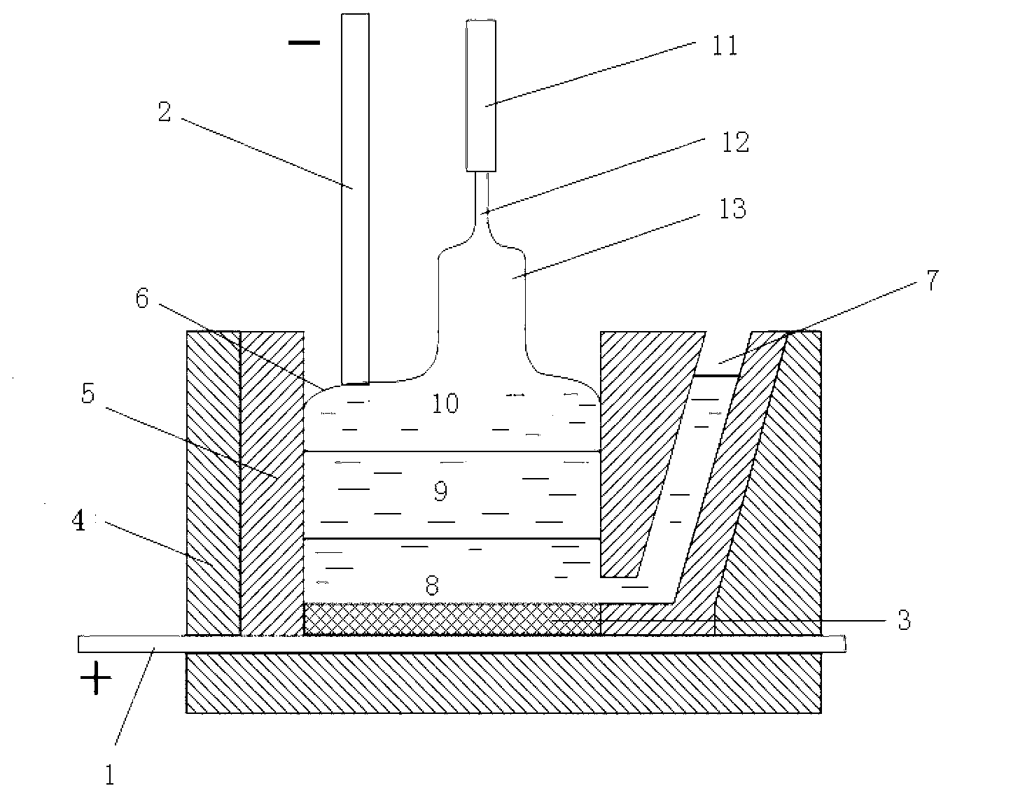
[0029] Step 4. Put the molten silicon alloy in the step (1) at the bottom of the electrolytic cell as an anode, the molten electrolyte in the step (2) is placed in the middle layer, and the thickness of the electrolyte is 10 cm, and the molten high-purity silicon in the step (3) is placed The uppermost layer is used as the cathode, and the electrolytic cell is a three-layer liquid electrolytic cell of "molten silicon alloy--molten electrolyte--molten high...

Embodiment 2

[0032] Step 1. Melting of the anode silicon-containing alloy: use metal Cu with a density greater than silicon and greater electronegativity than silicon and metallurgical grade silicon in a ratio of 3: 1, and use it as an anode after melting;

[0033] Step 2. Melting of the electrolyte: the electrolyte system uses MgF 2 with Na 2 SiO 3 The mixture is melted and used as electrolyte system for standby; among them, Na 2 SiO 3 The content is 10wt%,

[0034] Step 3. The initial raw material of the cathode is liquid high-purity silicon with a purity above 6N;

[0035] Step 4. Put the molten silicon alloy in the step (1) at the bottom of the electrolytic cell as the anode, and put the molten electrolyte in the step (2) in the middle layer, the thickness of the electrolyte is 5cm, and put the molten high-purity silicon in the step (3) The uppermost layer is used as the cathode, and the electrolytic cell is a three-layer liquid electrolytic cell of "molten silicon alloy - molten ...

Embodiment 3

[0038]Step 1. Melting of the anode silicon-containing alloy: use metal Cu with a density greater than silicon and greater electronegativity than silicon and industrial polysilicon wire cutting waste in a ratio of 2:2, and use it as an anode after melting;

[0039] Step 2. Melting of the electrolyte: the electrolyte system uses SrF 2 with BaSiF 6 The mixture, melted as electrolyte system, standby; among them, BaSiF 6 The content is 20wt%,

[0040] Step 3. The initial raw material of the cathode is liquid high-purity silicon with a purity above 6N;

[0041] Step 4. Put the molten silicon alloy in the step (1) at the bottom of the electrolytic cell as an anode, put the molten electrolyte in the step (2) in the middle layer, and the thickness of the electrolyte is 30 cm, and place the molten high-purity silicon in the step (3) The uppermost layer is used as the cathode, and the electrolytic cell is a three-layer liquid electrolytic cell of "molten silicon alloy--molten electrol...


PUM

PropertyMeasurementUnit
Thicknessaaaaaaaaaa
Thicknessaaaaaaaaaa
Thicknessaaaaaaaaaa

Abstract

The invention relates to a method for preparing high-purity monocrystalline silicon through electrolytic refining-liquid cathode in-situ directional solidification. The method disclosed by the invention comprises the steps of: taking a molten silicon-containing alloy as the anode of an electrolytic cell, placing fluoride electrolyte at the middle layer and placing molten high-purity silicon at the uppermost layer to serve as the cathode so as to form a three-layer liquid electrolytic tank with the molten silicon alloy, the molten electrolyte and the molten high-purity silicon from bottom to top, carrying out constant current electrolytic refining, carrying out in-situ czochralsk directional solidification on the cathode liquid high-purity silicon in the electrolytic refining process to further purify and directly preparing high-purity silicon into the high-purity monocrystalline silicon. The method has the advantages that the polycrystalline silicon is deposited in a liquid form, so that the problems that in the process of preparing solar grade polycrystalline silicon by using a molten salt electrolysis method, the silicon is deposited in a solid form, the product is easy in dendrite forming, the electrical conductivity is poor, the cathode solid-liquid interface is unstable, the deposition speed is low and the current efficiency is low are solved; the preparation flow of the monocrystalline silicon is shortened; and the manufacturing cost of solar grade polycrystalline silicon and monocrystalline silicon batteries can be reduced.

Description

technical field [0001] The invention relates to a method for directly preparing high-purity single-crystal silicon by combining electrochemical refining with in-situ directional solidification of liquid cathodes, in particular to a method for preparing high-purity single-crystal silicon by electrolytic refining-liquid cathode in-situ directional solidification. Background technique [0002] In recent years, energy issues have increasingly become a bottleneck restricting the development of the international society and economy. More and more countries have begun to develop solar energy resources, and the photovoltaic industry has become the fastest growing industry in the world. As the main application of the photovoltaic industry, solar cells play an important role in addressing the challenges of the global energy crisis and environmental pollution. [0003] To date, approximately 90% of solar cells are produced from high-purity crystalline silicon materials, including monoc...

Claims


Application Information

Patent Timeline
IPC IPC(8): C30B29/06C30B9/14
Inventor 焦树强胡月皎朱鸿民
Owner UNIV OF SCI & TECH BEIJING
Why Eureka
Try Eureka