
Preparation method of thermal barrier coating and thermal barrier coating prepared by preparation method

A technology of thermal barrier coating and solution, which is applied in the direction of coating, metal material coating process, liquid chemical plating, etc., and can solve the problem of lower thermal shock resistance of coating, lower thermal insulation performance of coating, and weak lamellar bonding and other issues to achieve the effects of improving productivity, simplifying cumbersome processes, and reducing costs

Active Publication Date: 2013-01-02
CHINESE ACAD OF AGRI MECHANIZATION SCI +1
View PDF4 Cites 12 Cited by
  • Summary
  • Abstract
  • Description
  • Claims
  • Application Information

AI Technical Summary

Problems solved by technology

The thermal barrier coating prepared by traditional APS has a layered structure, and the thermal insulation performance of the coating is better than that of EB-PVD coating. However, the interlayer cracks lead to weak bonding between the layers, which reduces the thermal shock resistance of the coating.
The survey shows that the thermal shock resistance of the vertical crack structure thermal barrier coating prepared by traditional APS is significantly better than that of the conventional structure coating prepared by APS, however, the vertical crack structure thermal barrier coating prepared by traditional APS High density, resulting in reduced thermal insulation performance of the coating

Method used


Image

  • Preparation method of thermal barrier coating and thermal barrier coating prepared by preparation method
  • Preparation method of thermal barrier coating and thermal barrier coating prepared by preparation method
  • Preparation method of thermal barrier coating and thermal barrier coating prepared by preparation method

Examples


Embodiment 1

[0049] Take yttrium nitrate solid and join in the zirconium acetate solution, make metal Zr ion concentration be 1mol / L in the solution, control the concentration of yttrium oxide in zirconia to be 7~8wt%, electromagnetic stirring at room temperature makes yttrium nitrate fully dissolve and Mix to obtain a YSZ solution precursor with a solute concentration of 9%.

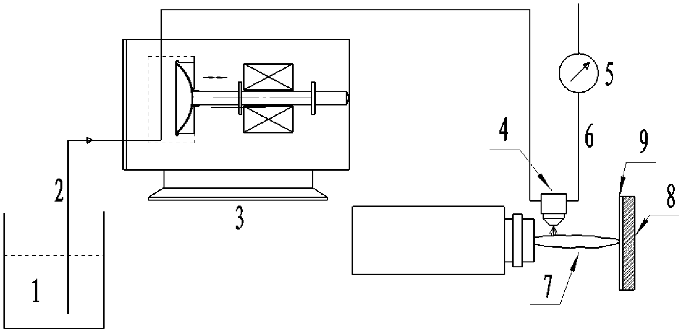
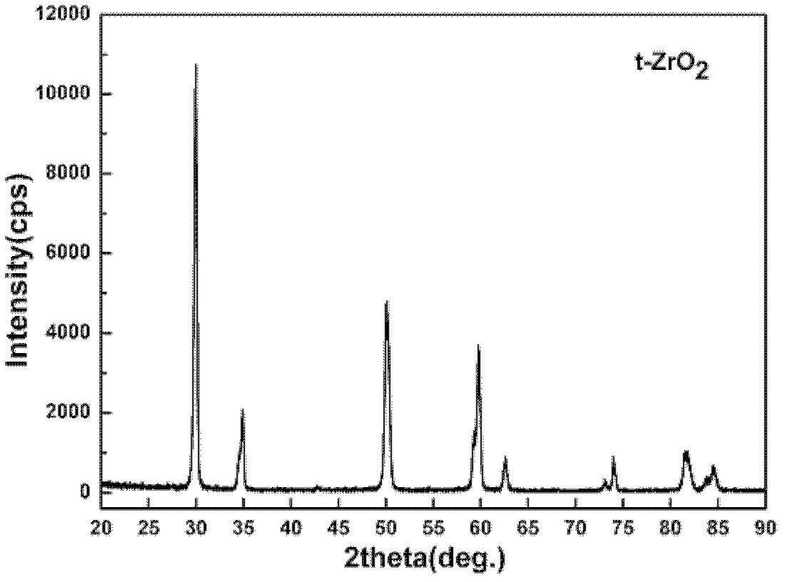
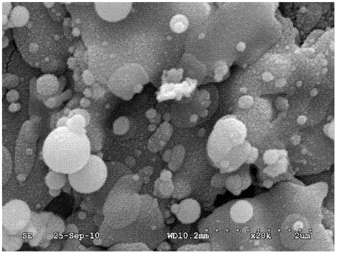
[0050] The prepared solution precursor was atomized through a two-flow atomization nozzle at a flow rate of 25ml / min and then sent into the plasma jet. A thermal barrier coating is formed on the substrate. The crystal structure and surface morphology of the coating were tested by X-ray diffraction (XRD) and scanning electron microscope, respectively. Such as Figure 2a As shown, the results show that: the coating is a single tetragonal phase structure, no monoclinic phase exists. Such as Figure 2b As shown, the results show that the coating is nanostructured and the grain size is less than 100nm.

Embodiment 2

[0052] Weigh the solid yttrium nitrate and add it to the zirconium acetate solution, so that the metal Zr ion concentration in the solution is 2.4mol / L, control the concentration of yttrium oxide in the zirconia to 7-8wt%, and stir electromagnetically at room temperature to fully dissolve the yttrium nitrate and mixed to obtain a YSZ solution precursor with a solute concentration of 23%. The prepared solution precursor is sent into the plasma jet through the two-flow atomization nozzle at a flow rate of 50ml / min under the atomization gas pressure of 0.2MPa. A series of processes such as decomposition and melting, and finally deposited on the superalloy substrate to form a thermal barrier coating. The coating microstructure was tested by scanning electron microscope (SEM), and the coating porosity was analyzed by image method. The result is as Figure 3a As shown, the results show that a vertical crack structure is formed in the coating, the pores are evenly distributed in th...

Embodiment 3

[0054] The solution precursor was prepared according to Example 2. The solution precursor is fed into the plasma jet at a flow rate of 25ml / min through a two-flow atomizing nozzle at an atomizing gas pressure of 0.1MPa, and deposited on the superalloy substrate to form a thermal barrier coating. The coating microstructure was examined by scanning electron microscopy (SEM). The result is as Figure 4a As shown, the results show that a vertical crack structure is formed in the coating, without transverse interlayer cracks, and the pores are evenly distributed in an island shape, and a large number of pores are smaller than 2 μm ( Figure 4b ).


PUM

PropertyMeasurementUnit
particle sizeaaaaaaaaaa
porosityaaaaaaaaaa

Abstract

The invention discloses a preparation method of a thermal barrier coating and the thermal barrier coating prepared by the preparation method. According to the method, a solution precursor composed of zirconates and yttrium salts is used as a spraying raw material. The solution precursor is atomized into liquid drops through a two-phase flow atomizing nozzle; and the liquid drops are sent for plasma jet, undergo plasma jet heating and acceleration and are deposited on a matrix to form the thermal barrier coating. The thermal barrier coating is nanostructured and has a vertical crack structure. The solution precursor liquid material replaces an agglomerated powder to be used as a spraying raw material, thus greatly simplifying tedious processes of traditional air plasma spraying for coating preparation. There are few technological processes for coating preparation in the invention, thus raising productivity and reducing cost. in addition, the coating structure is controllable and technical production can be realized. By the adoption of the prepared coating, defects of a coating prepared by traditional plasma spraying are eliminated, and a high-performance coating which satisfies special requirements can be prepared.

Description

technical field [0001] The invention relates to the preparation technology of thermal barrier coating. More specifically: a method for preparing a nanostructure thermal barrier coating with a vertical crack structure and uniformly distributed pores by replacing the solidified powder in the conventional plasma spraying process with a solution precursor. Background technique [0002] Thermal barrier coatings (TBCs) use the superior high temperature resistance, corrosion resistance and low thermal conductivity of ceramic materials to combine ceramics and metal substrates in the form of coatings to increase the working temperature of metal hot end parts and enhance the thermal performance of hot end parts. High temperature oxidation resistance and corrosion resistance, a surface protection technology that prolongs the service life of hot-end components and improves engine efficiency. Under the operating temperature of the engine, the creep life of the blade will be extended by ...

Claims


Application Information

Patent Timeline
Patent Type & Authority Applications(China)
IPC IPC(8): C23C4/10C23C4/12C23C18/02C23C4/11C23C4/134
Inventor 汪瑞军王世兴王伟平刘毅吕玉芬
Owner CHINESE ACAD OF AGRI MECHANIZATION SCI
Learn More