Ultrathin-wall microtubule production device and production method thereof

A technology for manufacturing devices and manufacturing methods, which is applied in the field of biosensors, and can solve problems such as rough tube walls, affecting the sensitivity of biodetectors, and inability to guarantee

Active Publication Date: 2013-12-04
TIANJIN UNIV
View PDF9 Cites 6 Cited by
  • Summary
  • Abstract
  • Description
  • Claims
  • Application Information

AI Technical Summary

Problems solved by technology

[0007] The first method is to melt and stretch first, and then corrode the inner wall. Although the required ultra-thin-walled quartz microtube resonator can be obtained, the tube wall is rough due to post-corrosion treatment of the microtube.
The Q value of the WGM sensing ultra-thin-walled quartz microtube resonator decreases, thereby affecting the sensitivity of the biodetector; at the same time, due to the limitation of the corrosion rate, the time to manufacture the WGM sensing ultra-thin-walled quartz microtube resonator is generally within 5 more than an hour
The second nanoscroll method, although it has the potential for large-scale integration, also cannot guarantee a sufficiently high Q value due to the corrosion of the surface.

Method used


Image

  • Ultrathin-wall microtubule production device and production method thereof
  • Ultrathin-wall microtubule production device and production method thereof
  • Ultrathin-wall microtubule production device and production method thereof

Examples


Embodiment 1

[0028] Example 1: Ultra-thin-walled microtube manufacturing device

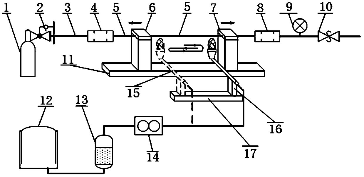
[0029] Such as figure 1 As shown, the production device includes a nitrogen gas cylinder 1, a pressure reducing valve 2, a PU tube 3, a caliber conversion device 4, a thick-walled microtube 5 and a left microtube holder 6, a right microtube holder 7, and a caliber conversion Device 8, high-precision barometer 9, back pressure valve 10, long-stroke high-precision micro-displacement stage 11, hydrogen and oxygen generator 12, gas dryer 13, gas flow controller 14, flame spray gun 15 and flame spray gun holding device 16 , Short-stroke high-precision micro-displacement stage 17.

[0030] among them:

[0031] Nitrogen gas cylinder: Standard nitrogen gas cylinder is used for the nitrogen gas (0.1MPa~1.0MPa) in the pressurized gas path inside the microtube.

[0032] Pressure reducing valve: installed at the outlet of the nitrogen gas cylinder to control the inlet pressure of the gas path behind it to prevent the pressure i...

Embodiment 2

[0048] Example 2: Manufacturing method of ultra-thin-walled microtubes

[0049] The manufacturing process of the above-mentioned ultra-thin-walled microtube manufacturing device is as follows:

[0050] 1. Install raw materials. Take a thick-walled quartz microtube 5 with a length of l (10mm~20mm), an outer diameter of D1 (100μm~700μm), and a wall thickness of d1 (30μm~60μm), and connect the left and right ends to the left and right diameter conversion devices respectively 4, 8, to make the overall gas path connected; after that, fix both ends of the thick-walled quartz microtube 5 on the left and right microtube holders 6, 7 respectively, and adjust the left and right microtube holders The devices 6, 7 make the microtube parallel to the axis of the guide rail of the long-stroke high-precision micro-translation stage 11;

[0051] 2. Nitrogen pressurization. Turn on the switch of the nitrogen cylinder 1 and adjust the size of the pressure reducing valve 2 so that the downstream gas ...

Embodiment 3

[0059] Embodiment 3: Application examples

[0060] The ultra-thin-wall micro-tube resonant cavity manufactured by the ultra-thin-wall micro-tube manufacturing device and method of the present invention can be applied to WGM-based optical microfluidic biosensing.

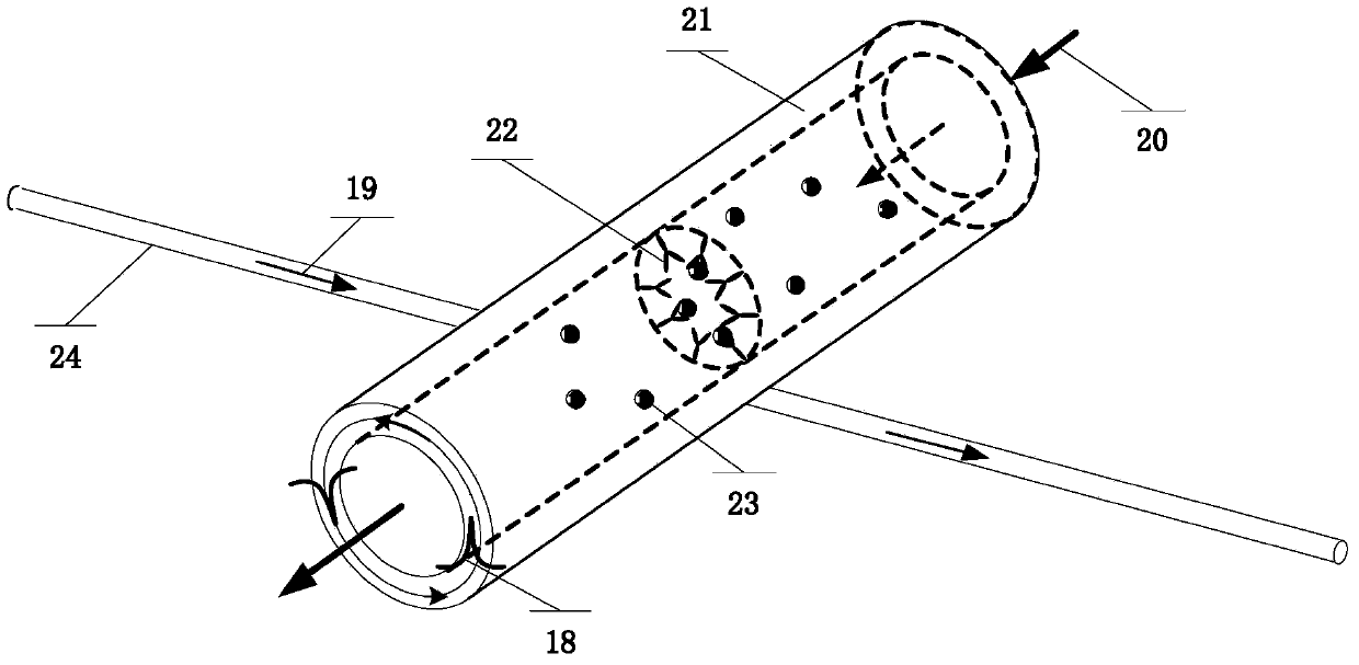
[0061] Its local sensor structure is like figure 2 As shown, the biological detection reagent 22 is solidified on the inner wall of the ultra-thin-walled microtube resonant cavity 21, and the microfluidic test sample 20 is transported from the ultra-thin-walled microtube resonant cavity 21. The ultra-thin-walled microtube resonant cavity 21 forms a micro-resonant cavity perpendicular to the axial direction in the tube wall, and the light waves propagating in the cavity penetrate into the microfluidic detection sample 20 in the ultra-thin-walled microtube resonant cavity 21 through the evanescent wave field for detection .

[0062] When the microfluid 20 transporting the biomolecule to be detected passes through the ultra-...


PUM

PropertyMeasurementUnit
thicknessaaaaaaaaaa

Abstract

The invention discloses an ultrathin-wall microtubule production device and a production method thereof. The ultrathin-wall microtubule production device comprises a nitrogen gas cylinder, a pressure reducing valve, a PU (poly urethane) tube, a caliber conversion device, a thick-wall microtubule, a left microtubule gripper, a right microtubule gripper, another caliber conversion device, a high-precision barometer, a back pressure valve, a long-stroke and high-precision micro displacement platform, a hydrogen-oxygen producing machine, a gas dryer, a gas flow controller, a flame gun, a flame-gun clamping device and a short-stroke and high-precision micro displacement platform. The production method includes that nitrogen with precisely-controlled barometric pressure enters an inner cavity of the microtubule, from the caliber conversion device, to apply outward pressure upon a tubule wall of the microtubule; oxyhydrogen with precisely-controlled flow rate forms oxyhydrogen flame, at a position of a nozzle of the flame gun, to evenly heat the thick-wall microtubule; the microtubule grippers with precisely-controlled speed and distance evenly stretch the microtubule to obtain the ultrathin-wall microtubule finally. The ultrathin-wall microtubule produced by the method is smooth in the tubule wall, a resonant cavity is constructed to ensure a good field evanescent function and a high Q value, and the time for producing one ultrathin-wall microtubule is less than 30 minutes.

Description

Technical field [0001] The invention relates to a biosensor of photobiology and chemical sensing technology, in particular to an ultrathin-walled microtube manufacturing device and a manufacturing method with a photomicrofluidic sensing resonant cavity. Background technique [0002] The label-free biosensor based on micro-resonance optical technology is directly used to measure molecular interactions, which can realize real-time observation of biomolecular interactions. Because there is no need for the analyte to be tested to have special properties such as fluorescence, characteristic absorption or scattering bands, the range of measurement objects is greatly expanded, and toxins, proteins, DNA, and even the entire cell behavior can be detected, which is useful for medical diagnosis, drug development, food monitoring, and environment Monitoring and other fields provide powerful analysis tools. [0003] The optical micro resonant cavity uses total reflection to completely confine ...

Claims


Application Information

Patent Timeline
Patent Type & Authority Applications(China)
IPC IPC(8): G01N21/01G01N21/41
Inventor 刘铁根江俊峰刘琨陈文杰于哲张学智樊茁刘文辉
Owner TIANJIN UNIV
Why Eureka
Try Eureka