Ultra-low emission circulating fluidized bed boiler with three stages of desulfurization systems

A circulating fluidized bed and desulfurization system technology, applied in chemical instruments and methods, separation methods, dispersed particle separation, etc., can solve the problems of poor quality of fly ash that cannot be comprehensively utilized, heavy transformation workload, and low desulfurization efficiency. The effect of high utilization rate of desulfurization agent, small modification workload and high desulfurization efficiency

Active Publication Date: 2013-12-18
HUANENG CLEAN ENERGY RES INST
View PDF7 Cites 14 Cited by
  • Summary
  • Abstract
  • Description
  • Claims
  • Application Information

AI Technical Summary

Problems solved by technology

[0010] Obviously, the existing technology has low desulfurization efficiency, high operating costs, and poor quality of fly ash that cannot be comprehensively util...

Method used


Image

  • Ultra-low emission circulating fluidized bed boiler with three stages of desulfurization systems

Examples


Embodiment 1

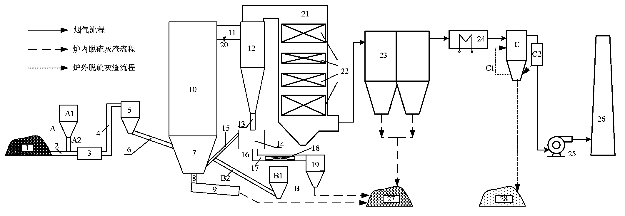
[0041] Such as figure 1 Shown is a newly built 300MW class circulating fluidized bed boiler with a three-stage desulfurization system. The combustion temperature of the boiler is 900°C, and the desulfurization agent addition system A in front of the furnace uses limestone particles with a median diameter of 3mm. District 7. The desulfurizer conveying system B in the furnace conveys limestone powder with a median diameter of 0.5 mm from the return pipe 15 to the dense-phase zone 7 of the furnace. The desulfurized flue gas in the furnace is cooled to 100°C by the exhaust gas temperature desuperheater 24, and then sent to the deep flue gas desulfurization system C for deep desulfurization. The desulfurization agent used in the deep flue gas desulfurization system C is slaked lime. The reducing agent nozzle 20 sprays the aqueous urea solution to the inlet flue 11 of the separator to further reduce the emission concentration of nitrogen oxides on the basis of the low-nitrogen com...

Embodiment 2

[0044] A newly built 135MW circulating fluidized bed boiler with a three-stage desulfurization system. The combustion temperature of the boiler is 935°C. The desulfurization agent addition system A in front of the furnace uses limestone particles with a median diameter of 2mm, and the desulfurizer delivery system B in the furnace uses limestone powder with a median diameter of 0.3mm. A desulfurizer is also added to improve the desulfurization efficiency. The total amount of 3% sodium chloride desulfurization enhancer reduces the decomposition rate of calcium sulfate during combustion and improves the desulfurization efficiency.

Embodiment 3

[0046] A remodeled 200MW circulating fluidized bed boiler. The boiler was originally equipped with a desulfurization agent delivery system B in the furnace. A pre-furnace desulfurization agent addition system A and a deep flue gas desulfurization system C were added to the boiler. Through three-stage desulfurization The final sulfur dioxide emission concentration of the boiler is lower than 100mg / m 3 .


PUM

PropertyMeasurementUnit
Particle sizeaaaaaaaaaa
Median diameteraaaaaaaaaa
Particle sizeaaaaaaaaaa

Abstract

The invention discloses an ultra-low emission circulating fluidized bed boiler with three stages of desulfurization systems. The three stages of desulfurization systems include a front desulfurizing agent adding system, an inner desulfurizing agent conveying system and a deep flue gas desulfurization system, the front desulfurizing agent adding system is positioned in a coal yard area in front of the boiler, the inner desulfurizing agent conveying system is positioned in a plant area of the boiler, and the deep flue gas desulfurization system is positioned in a tail area of the boiler; the front desulfurizing agent adding system comprises a front desulfurizing agent bin and a front desulfurizing agent gravimetric adding machine below the front desulfurizing agent bin, the inner desulfurizing agent conveying system comprises an inner desulfurizing agent bin and an inner desulfurizing agent conveying feeder below the inner desulfurizing agent bin, and an efficient desulfurizing agent circulating system and a flue gas supplementary dust removing device are further arranged on the deep flue gas desulfurization system. The ultra-low emission circulating fluidized bed boiler has the advantages that the systems are simple, are low in running energy consumption, can be regulated and controlled easily and conveniently, are high in desulfurizing agent utilization rate and desulfurization efficiency and free of water resource consumption and are widely suitable to be used with new circulating fluidized bed boilers in an environment-friendly manner and to modify existing circulating fluidized bed boilers in an environment-friendly manner, and space and equipment investment can be effectively saved.

Description

technical field [0001] The invention relates to the technical field of circulating fluidized bed boilers, in particular to an ultra-low emission circulating fluidized bed boiler with a three-stage desulfurization system. Background technique [0002] my country is the world's major coal producer and consumer, and also a country that uses coal as its primary energy source. The flue gas produced by coal combustion contains a large amount of pollutants such as sulfur dioxide, nitrogen oxides and heavy metals, causing serious environmental pollution. According to the 2012 Bulletin on the State of the Environment in China, the national emission of sulfur dioxide in waste gas was as high as 21.176 million tons in 2012, and thermal power generation has always been one of the main sources of sulfur dioxide emission. [0003] In order to strengthen environmental protection and achieve the goal of energy conservation and emission reduction, the "Emission Standard of Air Pollutants fo...

Claims


Application Information

Patent Timeline
IPC IPC(8): F23J15/02B01D53/82B01D53/50
Inventor 黄中徐正泉郭涛
Owner HUANENG CLEAN ENERGY RES INST
Why Eureka
Try Eureka