Boilers Using Pyrolysis Vaporization Combustion Method

A combustion method and pyrolysis technology, applied in the field of boilers, can solve the problems of large differences in particle size, specific gravity, ash content, loose organizational structure, and impermanence, and achieve the effect of wide application range, small resistance and reducing dust effect.

Active Publication Date: 2015-12-09
韩枫
View PDF7 Cites 0 Cited by
  • Summary
  • Abstract
  • Description
  • Claims
  • Application Information

AI Technical Summary

Problems solved by technology

[0004] 1. Since most of the garbage is composed of a mixture of various organic substances and low-quality combustibles mixed with a lot of non-combustible materials, the existing combustion technology has low combustion efficiency for this type of garbage and produces secondary pollution, especially It is the pollution problem of Dioxins
[0005] 2. The existing boiler products are all designed for a specific fuel. Due to the different shapes of garbage and biomass, the particle size, specific gravity, and ash content vary greatly, and it is difficult to establish a stable combustion process. Situation point
[0006] 3. Due to the loose tissue structure of the straw, which contains inorganic substances such as silicon, potassium, magnesium, phosphorus and calcium, it is in the state of molten fine glass during the combustion process, and after entering the low temperature zone, silicate deposits are formed and solidified in the Reduce the heat conduction effect on the structural wall, where alkali metals will cause corrosion of the structural wall

Method used


Image

  • Boilers Using Pyrolysis Vaporization Combustion Method
  • Boilers Using Pyrolysis Vaporization Combustion Method
  • Boilers Using Pyrolysis Vaporization Combustion Method

Examples


no. 1 example

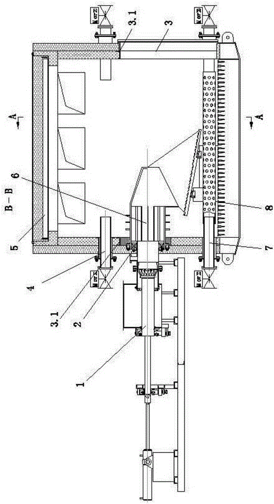
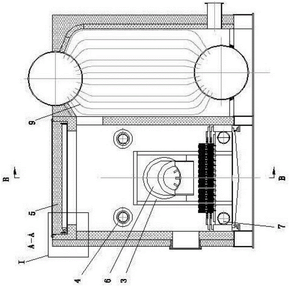
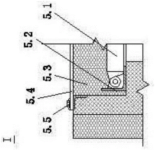
[0081] (refer to figure 1 , figure 2 , image 3 ) There is a furnace wall opening 3 on the furnace wall on both sides of the furnace, a furnace wall opening frame 3.1 is arranged on the edge of the opening, an explosion-proof door 5 is arranged on the furnace, the explosion-proof door panel 5.1 is placed on the explosion-proof door frame 5.2, and thermal insulation material 5.3 is laid on it , and then lay the sealing film 5.4, and fix the sealing film with bead 5.5. There is an ember grate 8 in the lower part of the hearth. A channel type pyrolysis device 6 is installed inside the furnace, and a piston type feeding device 1 is installed outside the furnace. The heat exchanger 9 has no restriction on selection and arrangement. Channel type pyrolysis device 6 is made up of pyrolysis cylinder 6.1, pyrolysis grate 6.2 (referring to Figure 4-Figure 8 ). The pyrolysis cylinder is divided into two sections, one section is cylindrical, with heat conducting fins 6.1.2 on the ...

no. 2 example

[0091] Second embodiment (refer to Figure 28 )

[0092] On the basis of the above-mentioned embodiments, a gas burner chamber 10 is set up separately on the side of the furnace to improve the dust removal effect before the heat exchanger. The heat exchanger can use heat pipes 11 for heat transfer, and can be designed as a hot blast stove for heating air.

no. 3 example

[0094] Adopt tank-type pyrolysis device, form track support 19 with refractory brick stacking certain height on burner grate 8, track crossbeam 13 (referring to Figure 31 , Figure 32 ) on the track bracket 19, the track beam 13 has a card slot 13.1, the web 14.1 of the track bar 14 is stuck in the card slot 13.1, the track bar 14 is fixed horizontally, and there is a shoulder 14.2 on the web 14.1 of the track bar 14 Stand on the side of the crossbeam and fix the track bar 14 vertically.

[0095] Pyrolysis tank 12 (refer to Figure 33 , Figure 34 , Figure 35 ) is composed of chassis car 12.1, pyrolysis grate 12.2, basket 12.3, outer cover 12.4, etc., chassis car 12.1 is composed of lifting beam 12.1.1, car beam 12.1.2, car frame 12.1.3, basket limit gear 12.1. 4. Composition of wheels 12.1.5. Pyrolysis grate 12.2 (see Figure 36 , Figure 37 , Figure 38 ) has a vertical bar 12.2.1 and a horizontal bar 12.2.2. The vertical bar and the horizontal bar are fixed togeth...


PUM


Abstract

A boiler by the adoption of the pyrolysis vaporization combustion method can be used for pyrolysis of coal, refuse and biomass and combustion of pyrolysis products. A channel type pyrolysis device or a tank type pyrolysis device is arranged in a hearth of the boiler. When the temperature of fuel in the pyrolysis device gradually rises from the normal temperature to the pyrolysis temperature in the hearth, a pyrolysis reaction starts, gas-solid separation is completed, the temperature of the solid coal on the surface layer rises to be higher than the ignition temperature, ignition starts when the solid coal encounters the air, and then the solid coal falls into a solid combustion area to be completely combusted; produced pyrolysis gas passes through coal fire to come out, combustible components in the pyrolysis gas starts to combust when encountering the air, and flames rise and burn along the side wall of a pyrolysis cylinder; meanwhile, the pyrolysis cylinder is heated so that the pyrolysis reaction of the fuel in the pyrolysis cylinder can continue, and the fuel can be completely combusted in a gas combustion area finally. The boiler by the adoption of the pyrolysis vaporization combustion method can meet the conditions required by the 3T+E combustion technology, as a result, formation of dioxin can be controlled, and boilers with different properties and specifications can be designed according to different specific requirements of users.

Description

technical field [0001] The invention relates to a boiler using a pyrolysis vaporization combustion method, in particular to a boiler capable of pyrolyzing coal, garbage and biomass and burning pyrolysis products. Background technique [0002] Due to the increasing shortage of coal resources, countries all over the world are researching waste and biomass combustion utilization technologies to solve the problems caused by the energy crisis and also solve the problem of environmental pollution. [0003] As far as the current stage is concerned, the bottleneck problems restricting the burning and utilization of waste and biomass are: [0004] 1. Since most of the garbage is composed of a mixture of various organic substances and low-quality combustibles mixed with a lot of non-combustible materials, the existing combustion technology has low combustion efficiency for this type of garbage and produces secondary pollution, especially It is the pollution problem of dioxin (Dioxins...

Claims


Application Information

Patent Timeline
Patent Type & Authority Patents(China)
IPC IPC(8): F23B90/06
Inventor 韩枫
Owner 韩枫
Why Eureka
Try Eureka