Forked liquid crystal grating preparation method and application of forked liquid crystal grating in vortex beam
A technology of fork-shaped grating and liquid crystal grating, which is applied in the direction of diffraction grating, optics, nonlinear optics, etc., to achieve the effects of high light energy conversion efficiency, low technology implementation cost, and saving mask production cost
- Summary
- Abstract
- Description
- Claims
- Application Information
AI Technical Summary
Problems solved by technology
Method used
Image
Examples
Embodiment 1
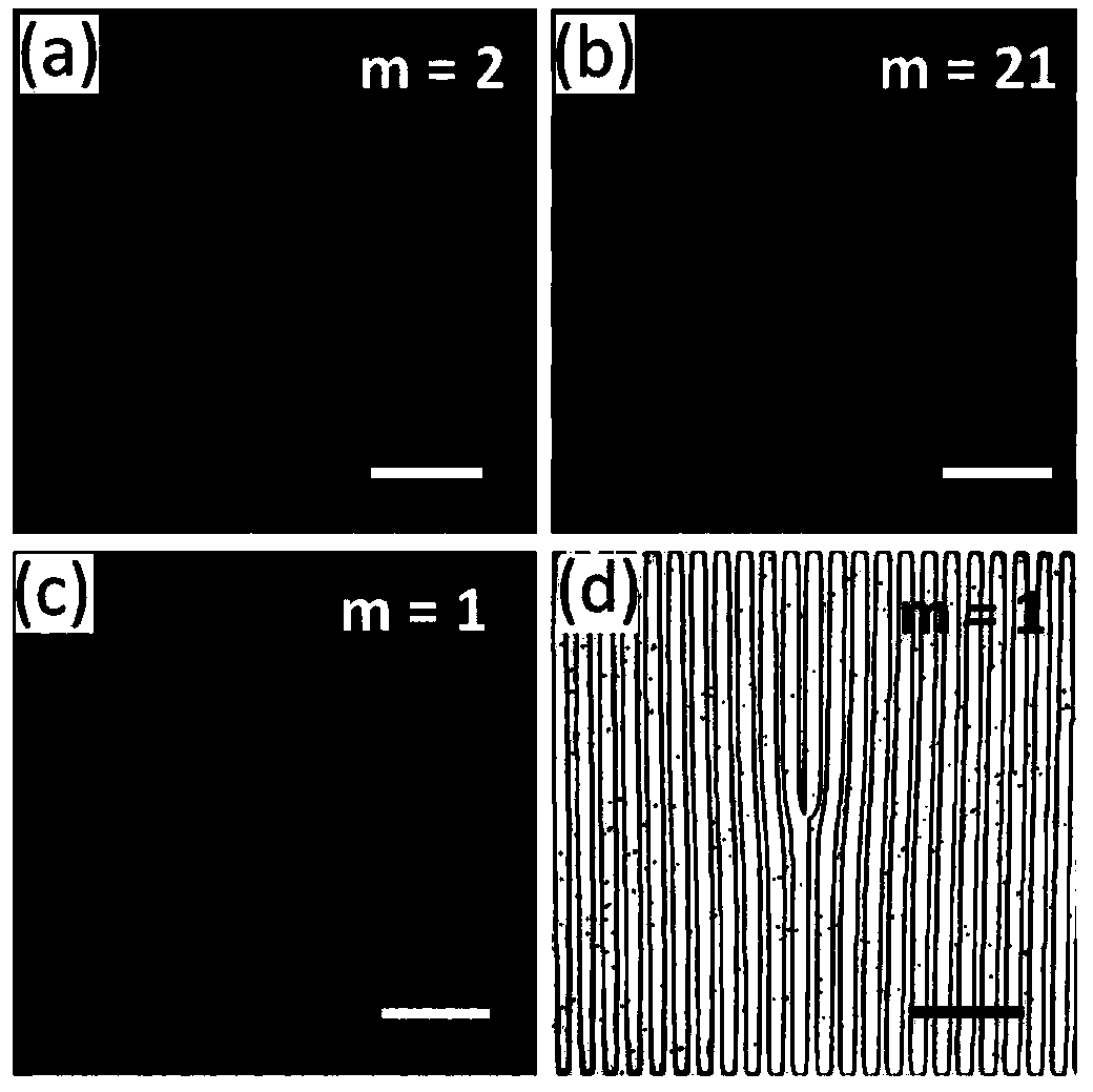
[0046] This embodiment realizes the patterning of the fork grating and the detection of the diffraction spot of the vortex beam on the TN type liquid crystal cell.
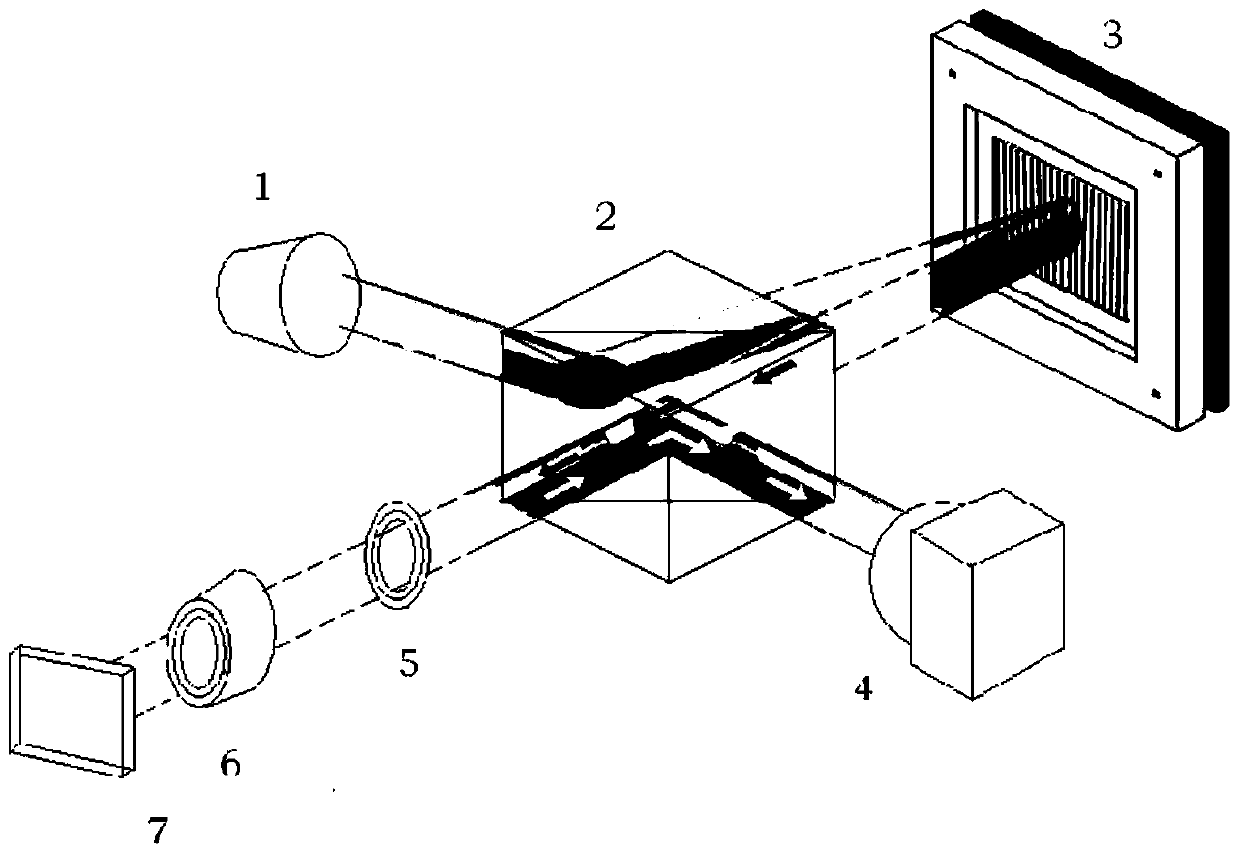
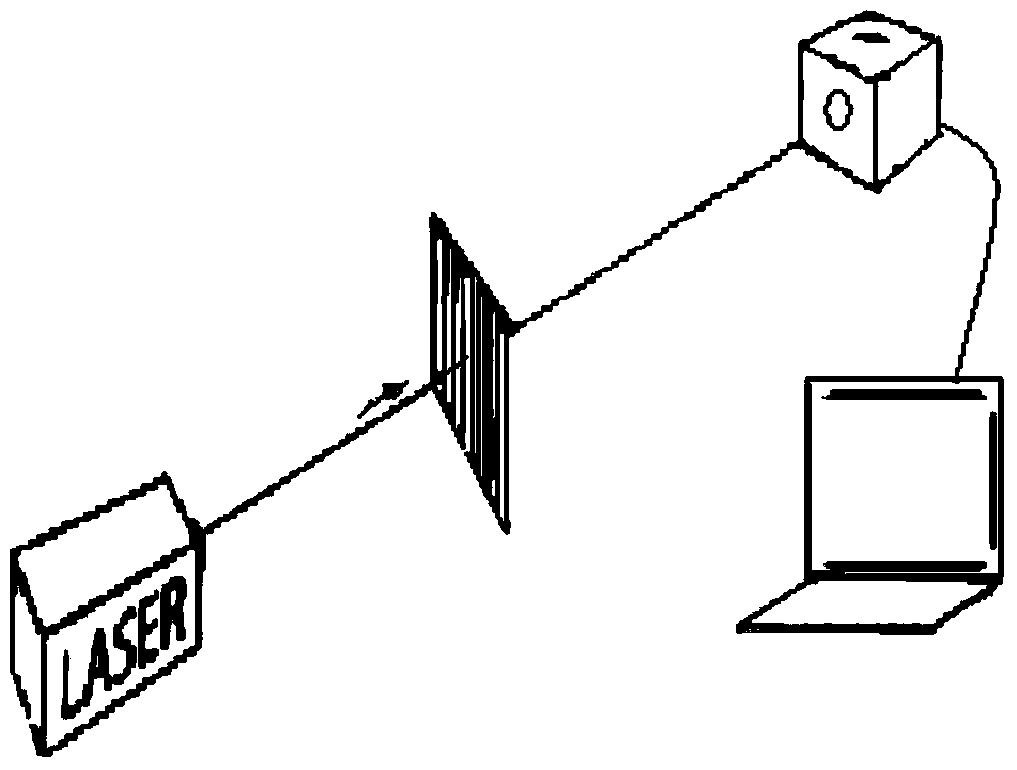
[0047] The CNC micromirror array lithography system is composed of: 405±10nm blue LED light source, through a beam splitting prism (size 25mm×25mm), evenly irradiates to DMD (1024×768 pixels, each pixel 13.68μm, best matching ultraviolet and Blu-ray band), the computer transmits the image control signal to the DMD signal input terminal through the CAD software (constituting the numerical control device); magnification 10 times) miniaturization, a sub-wavelength metal wire grid polarizer (diameter 50mm, extinction ratio greater than 2000:1) is placed 5cm in front of the sample stage; the focus monitoring component is the beam splitting prism and CCD imaging device in the real-time monitoring system ( The industrial ultraviolet-visible-near-infrared imaging CCD is selected and connected to the computer terminal thro...
Embodiment 2
[0053] This embodiment realizes the patterning of the fork-shaped grating on the orthogonal PA type liquid crystal cell.
[0054] The previous exposure steps are the same as in Example 1, the difference is that firstly the two pieces of glass sheets exposed for the first time are glued into a box, and then taken to the DMD system for secondary exposure of the fork-shaped grating pattern. The direction of the secondary exposure is perpendicular to the direction of the primary exposure. The method of making the box and filling the liquid crystal is the same as that of Embodiment 1. Under this method, the liquid crystal molecules in the re-exposed area and the non-re-exposed area in the liquid crystal cell are in parallel PA orientation, but the two orientations are orthogonal to each other. The advantage of this arrangement of liquid crystal molecules is that the diffraction spots and diffraction efficiency produced by it are not dependent on the polarization of incident light....
Embodiment 3
[0056] This embodiment implements the patterning of the fork grating on the orthogonal HAN type liquid crystal cell and measures the diffraction efficiency of the vortex beam diffraction spot of the incident light of different polarization states and different wavelengths. Changing the exposure pattern can realize the rewritable characteristics of the vortex beam.
[0057] The exposure treatment of one of the glass sheets to be made into a liquid crystal cell is the same as in Example 1, and the rubbing alignment treatment is performed on the other sheet. Firstly, the cleaning work of the glass sheet is the same as that in Example 1, and then the PI vertical alignment agent is spin-coated. It should be noted that the PI vertical alignment agent needs to be taken out of the refrigerator 3 to 4 hours before use, and it can be opened and used after it returns to room temperature. Spin-coating parameters were low-speed spin-coating for 6 seconds at a speed of 300 rpm, high-speed ...
PUM
 Abstract
Description
Claims
Application Information
 - R&D
- Intellectual Property
- Life Sciences
- Materials
- Tech Scout
- Unparalleled Data Quality
- Higher Quality Content
- 60% Fewer Hallucinations
Browse by: Latest US Patents, China's latest patents, Technical Efficacy Thesaurus, Application Domain, Technology Topic, Popular Technical Reports.
© 2025 PatSnap. All rights reserved.Legal|Privacy policy|Modern Slavery Act Transparency Statement|Sitemap|About US| Contact US: help@patsnap.com


