Electronic component, production method therefor, and sealing material paste used therein

A technology for sealing materials and electronic parts, applied in the field of electronic parts, can solve the problems of slow penetration of water molecules, high bonding temperature, insufficient gas barrier properties, etc., and achieve the effect of reducing devitrification, reducing thermal damage, and effective manufacturing

Inactive Publication Date: 2014-10-01
HITACHI CHEM CO LTD
View PDF12 Cites 6 Cited by
  • Summary
  • Abstract
  • Description
  • Claims
  • Application Information

AI Technical Summary

Problems solved by technology

However, since the gas-barrier property (airtightness) is not sufficient for bonding with resin, water molecules permeate slowly, and sufficient reliability cannot be obtained.
On the other hand, although a sealing material using low-melting glass can be joined with high gas barrier properties (airtightness), it requires a significantly higher joining temperature than resin sealing materials.

Method used


Image

  • Electronic component, production method therefor, and sealing material paste used therein
  • Electronic component, production method therefor, and sealing material paste used therein
  • Electronic component, production method therefor, and sealing material paste used therein

Examples


Embodiment 1

[0062] In this example, the composition and characteristics of the low-melting-point glass contained in the sealing material were studied. Examples are shown in Tables 1 to 4, and Comparative Examples are shown in Table 5. In the preparation of the low-melting point glasses shown in Table 1 to Table 5, reagent V manufactured by High Purity Chemical Research Laboratory was used. 2 o 5 , TeO 2 ,P 2 o 5 , Fe 2 o 3 、WO 3 、MoO 3 , Nb 2 o 5 、 Ta 2 o 5 , MnO 2 , Sb 2 o 3 、 Bi 2 o 3 , ZnO, SrCO 3 、BaCO 3 、Ag 2 O and K 2 CO 3as raw material. These raw materials were compounded and mixed in a specific amount to a total of 200 g, put into a platinum crucible, and heated to 900-1000°C in an electric furnace at a temperature increase rate of 5-10°C / min to melt. In order to form a uniform glass at this temperature, the raw materials were held for 2 hours while being stirred. Subsequently, the crucible is taken out, and the raw materials are flowed onto a stainless st...

Embodiment 2

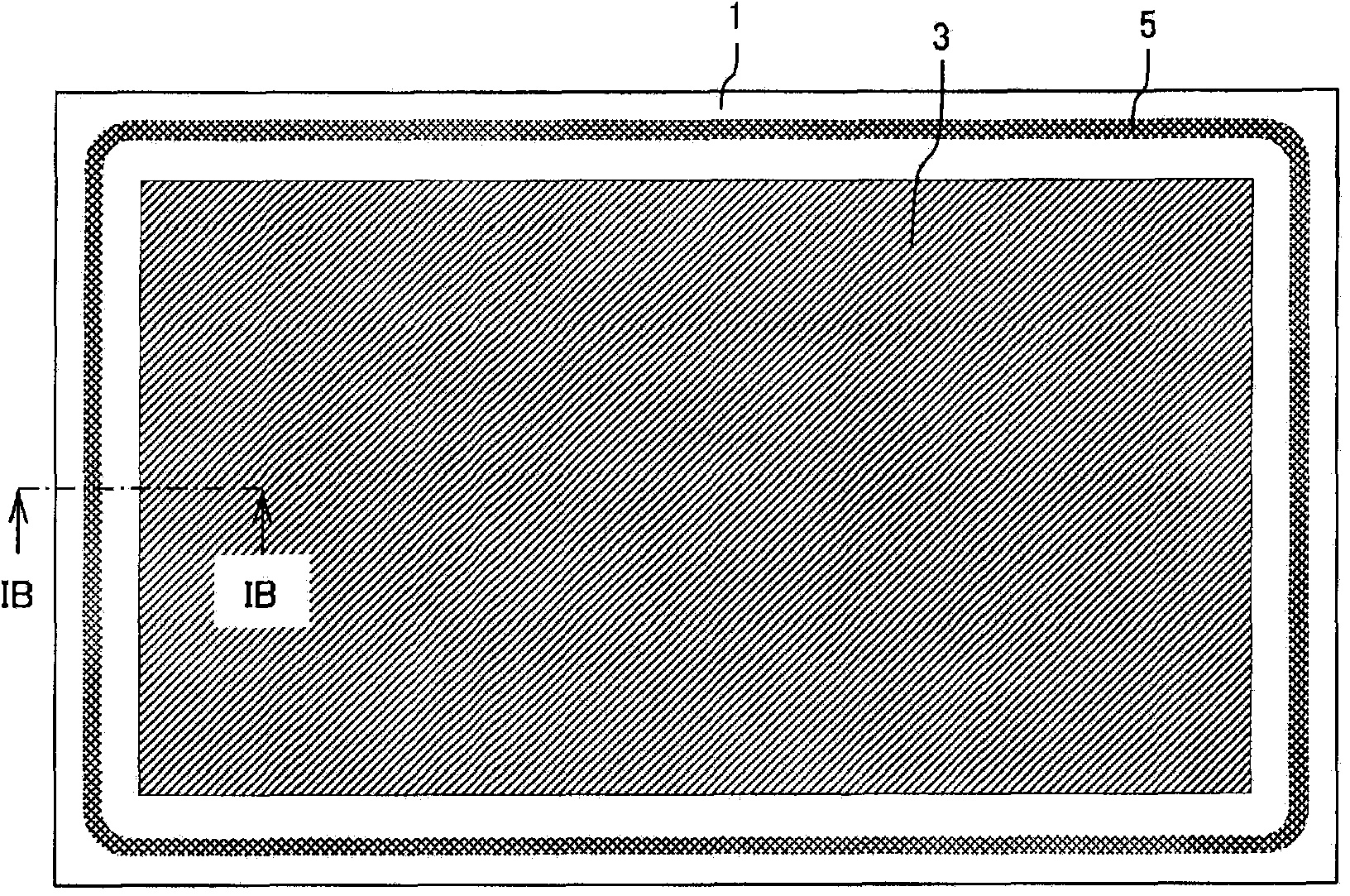
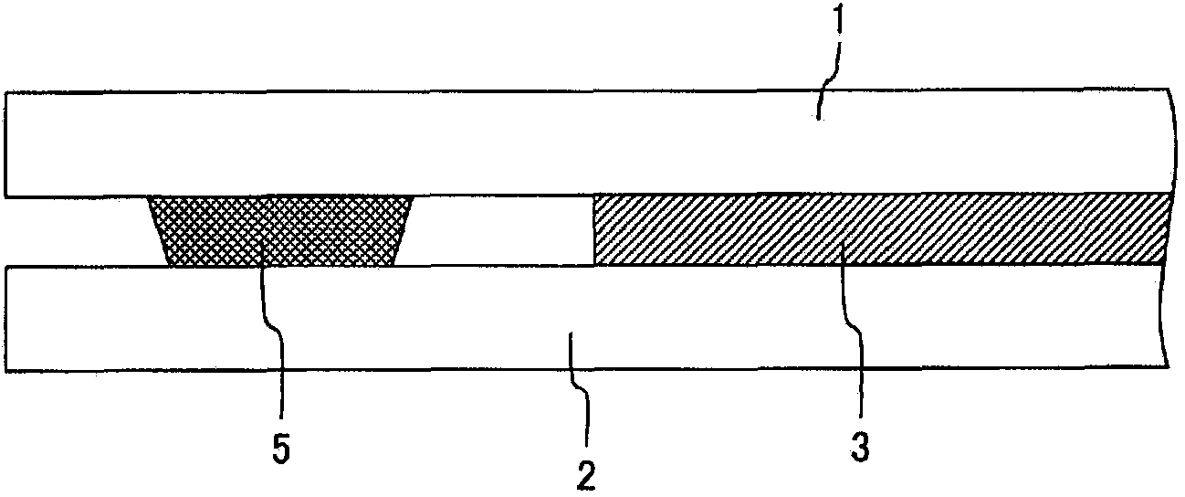
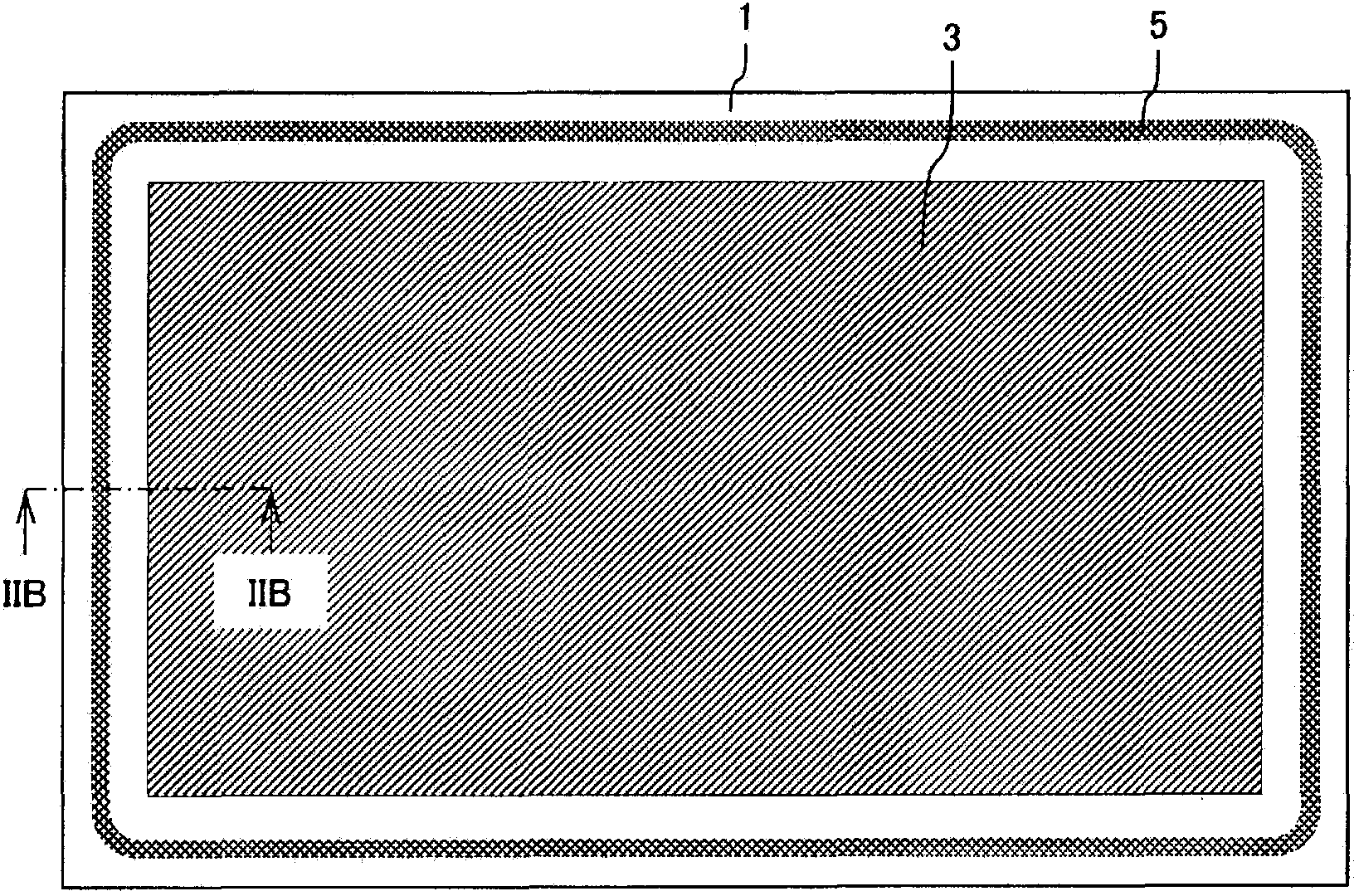
[0071] In this example, using the low-melting-point glass of Example G19 shown in Table 2 and a glass piece as a transparent substrate, a laser sealing experiment was performed. A sealing material paste was prepared using a jet mill to obtain G19 low-melting glass powder having an average particle diameter of 3 μm or less, a resin binder, and a solvent. Nitrocellulose was used as the resin binder, and butyl carbitol acetate was used as the solvent. Using this sealant paste, screen printing method such as Figure 11 As shown in , the sealing material paste was applied to the outer peripheral portion of the transparent substrate, and after drying, the sealing material paste was fired at 380° C. for 30 minutes in the air. The line width of the sealing material 5 formed on the transparent substrate 1 was 1.5 mm, and the fired film thickness thereof was adjusted by changing the coating amount to be about 5, 10, 20, and 30 μm, respectively. Such as Figure 12 As shown in , the tr...

Embodiment 3

[0077] In this embodiment, the transparent substrate uses 50×l0 -7 / °C coefficient of thermal expansion of the glass substrate. As the low-melting-point glass contained in the sealing material, Example G43 shown in Table 3 was used. Furthermore, zirconium phosphate tungstate (Zr 2 (WO 4 )(PO 4 ) 2 ), niobium oxide (Nb 2 o 5 ) and silicon (Si). Next, the same laser sealing experiment as in Example 2 was implemented.

[0078] First, G43 low-melting glass powder crushed with a jet mill to an average particle size of 3 μm or less, and Zr powder with an average particle size of about 5 μm 2 (WO 4 )(PO 4 ) 2 , Nb 2 o 5 Or Si filler particles, resin binder, and solvent to make sealing material paste. In addition, the content of the filler particles was set to 15, 25, 35, and 45 parts by volume with respect to 100 parts by volume of the low-melting glass of G43, respectively. The low melting point glass G43 used has a density of 3.53g / cm 3 , Zr 2 (WO 4 )(PO 4 ) 2 T...


PUM

PropertyMeasurementUnit
softening pointaaaaaaaaaa
thicknessaaaaaaaaaa
particle sizeaaaaaaaaaa

Abstract

The invention relates to an electronic component, production method therefor, and sealing material paste used therein. The electronic component has an organic member (3) between two transparent substrates (1, 2). The outer peripheral sections of the two transparent substrates (1, 2) are bonded using a sealing material (5) that comprises low-melting-point glass. The low-melting-point glass comprises vanadium oxide (V2O5), tellurium oxide (TeO2), phosphorus oxide (P2O5), and iron oxide (Fe2O3), and in terms of oxide content, corresponds to the following: V2O5+TeO2+P2O5+Fe2O3>=75 mass%, and V2O5>TeO2>P2O5>Fe2O3 (in mass%).

Description

technical field [0001] The present invention relates to an electronic component in which an organic element or an organic material is housed between two transparent substrates, and the outer periphery thereof is bonded using a sealing material. Background technique [0002] There are electronic components in which organic elements and organic materials are placed between two transparent substrates. In this electronic component, in order to protect these organic elements and organic materials from moisture, water, etc., the outer peripheries of two transparent substrates are bonded with a resin sealing material, or a desiccant is provided inside the electronic component. However, since the gas-barrier property (airtightness) is insufficient in the joining by resin, water molecule permeates slowly, and sufficient reliability cannot be obtained. On the other hand, although a sealing material using a low-melting glass can be joined with high gas barrier properties (airtightness...

Claims


Application Information

Patent Timeline
Patent Type & Authority Applications(China)
IPC IPC(8): H05B33/04C03C8/24H01L51/52H05B33/10
CPCC03C8/24H01L51/5246H05B33/10H05B33/04Y02E10/542C03C3/21Y02P70/50H10K50/8426
Inventor 内藤孝青柳拓也立薗信一吉村圭桥场裕司泽井裕一藤枝正
Owner HITACHI CHEM CO LTD
Why Eureka
Try Eureka