
Ceramic reinforced metal matrix composite welding layer plasma overlaying preparation method

A metal matrix composite, plasma stack technology, applied in the direction of plasma welding equipment, metal processing equipment, welding equipment, etc., can solve the problems of confinement of external powder feeding space, destruction of plasma flame stability, etc., to improve utilization rate and reduce defects trend, reducing the effect of direct burning loss

Inactive Publication Date: 2014-10-15
WUHAN UNIV OF TECH
View PDF6 Cites 21 Cited by
  • Summary
  • Abstract
  • Description
  • Claims
  • Application Information

AI Technical Summary

Problems solved by technology

However, plasma surfacing, as a relatively promising hardfacing layer preparation technology, has encountered great difficulties when using similar methods to inject reinforcing particles into the tail.
First of all, the distance between the surfacing nozzle and the workpiece to be welded is much smaller than the distance between the laser and the workpiece in the laser method, which makes the space of the external powder delivery on the surfacing welding more constrained; secondly, unlike the surface molten pool formed by the laser, the plasma There is a strong ion airflow above the molten pool generated by the flame, which makes it difficult for ceramic powder to be sent into the molten pool from the outside; thirdly, due to the different forms of plasma and laser energy, during plasma surfacing welding, the external powder airflow is very negative to the plasma flame. The stability is also prone to damage

Method used

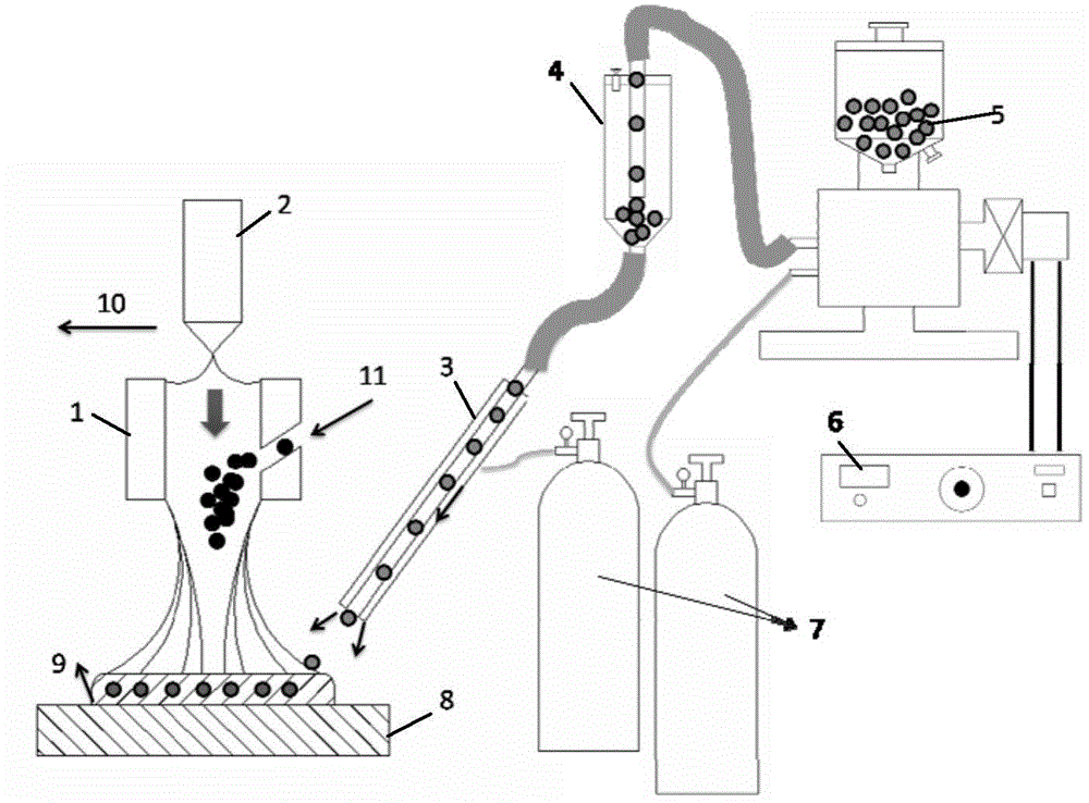
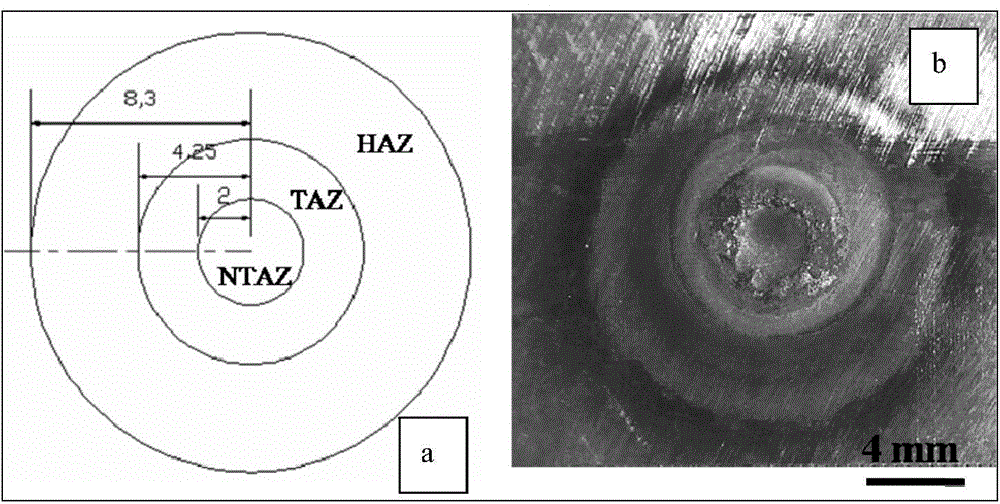
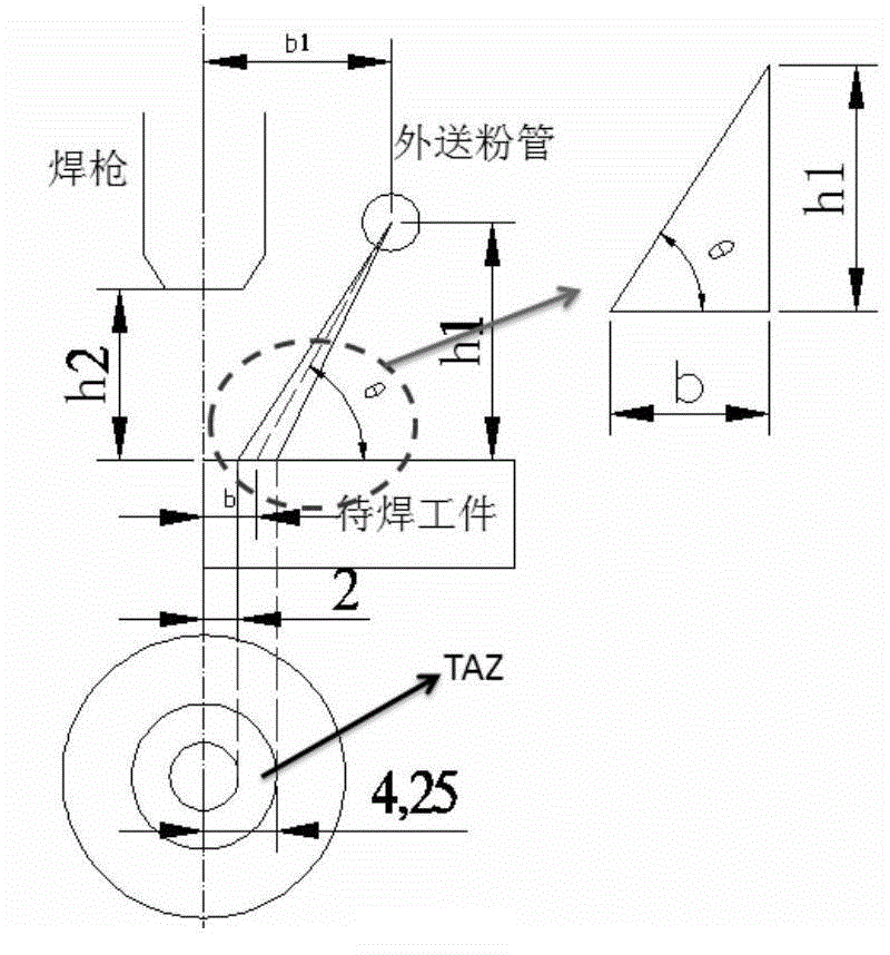

Image

  • Ceramic reinforced metal matrix composite welding layer plasma overlaying preparation method
  • Ceramic reinforced metal matrix composite welding layer plasma overlaying preparation method
  • Ceramic reinforced metal matrix composite welding layer plasma overlaying preparation method

Examples


Embodiment 1

[0021] Example 1: For the silicon carbide reinforced cobalt-based system, the plasma surfacing welding transfer arc current is 130A, the non-arc voltage is DC25v, the diameter of the tungsten electrode 2 is 4mm, the swing amplitude of the welding torch is 22mm, the swing frequency of the welding torch is 22c / min, and the welding torch walks The speed is 45mm / min, such as figure 1 Shown is the torch head walking direction 10, the distance between the workpiece to be welded and the torch nozzle 1 is 8mm, the argon gas flow rate for conveying the metal alloy powder is 5L / min, the powder feeding rate of the synchronous powder feeder is 10g / min, and the external powder feeder The powder feeding rate is 5g / min, the ion gas argon flow rate is 3L / min, and the shielding gas argon flow rate is 6L / min (both the welding torch and the external powder feeding pipe pass shielding gas to protect the molten pool). The flow rate of argon gas for external powder delivery is 5L / min, the distance ...

Embodiment 2

[0022] Example 2: For silicon carbide reinforced nickel-based system, plasma surfacing welding transfer arc current is 120A, non-arc voltage is DC25v, tungsten pole diameter is 4mm, welding torch swing is 22mm, welding torch swing frequency is 22c / min, welding torch travel speed The distance between the workpiece to be welded and the nozzle of the welding torch is 10mm, the argon gas flow rate for conveying the metal alloy powder is 5L / min, the powder feeding rate of the synchronous powder feeder is 20g / min, and the powder feeding rate of the external powder feeder is 10g / min, the flow rate of ion gas argon is 3L / min, and the flow rate of shielding gas argon is 6L / min (both the welding torch and the external powder delivery pipe pass shielding gas to protect the molten pool). The flow rate of argon gas for external powder delivery is 5L / min, the distance h1 between the nozzle center of the external powder delivery pipe and the workpiece to be welded is 12mm, and the distance b...

Embodiment 3

[0023] Embodiment 3: For the same material system and process parameters as in Embodiment 1, the difference is that silicon carbide not coated by electroless plating is selected for a comparative test. The microstructure of the prepared solder layer is shown in Figure 5 shown. It shows that silicon carbide without coating treatment can not prepare chromium carbide reinforced composite welding layer well, and the carbides generated are mainly at the top of the welding layer, and the distribution is uneven. Example 3 shows that silicon carbide is processed by electroless plating coating Important means in the method of the present invention.


PUM

PropertyMeasurementUnit
particle sizeaaaaaaaaaa
particle diameteraaaaaaaaaa

Abstract

The invention provides a ceramic reinforced metal matrix composite welding layer plasma overlaying preparation method, which comprises the following steps: 1) pretreatment before overlaying; 2) melting, injecting and feeding of powder outside a gun; 3) performing plasma overlaying to prepare a ceramic reinforced metal matrix composite welding layer. The ceramic reinforced metal matrix composite welding layer plasma overlaying preparation method has the beneficial effects that the utilization ratio of reinforced ceramic in the overlaying process is increased, the chemical reaction rate of the reinforced ceramic and metal molten is lowered due to chemical coating, the trend that the defect is generated in the composite welding layer due to the sharp reaction between the reinforced ceramic and the metal interface is reduced, meanwhile, the composite welding layer prepared by the method has a lot of in situ generated large granular carbides, and thus the mechanical properties (such as strength, hardness and wear resistance) and thermal physical properties (such as thermal expansion coefficient, high temperature oxidation resistance and thermal intensity) of the composite welding layer are significantly improved.

Description

technical field [0001] The invention belongs to the technical field of surfacing to prepare hard-facing welding layers, and in particular provides a method for preparing a ceramic-reinforced metal-matrix composite welding layer by plasma surfacing, which can expand the types of reinforced ceramic particles that can be used for surfacing, and significantly improve metal-matrix composite welding. layer surface properties. Background technique [0002] Ceramic-reinforced metal-matrix composites have attracted widespread attention because they have both the plasticity and toughness of metals and the stiffness and hardness of ceramics, and can be used in more severe service conditions. In recent years, ceramic-reinforced metal matrix composites are considered to be one of the most promising functional materials in aerospace, automotive and other structural material applications. Taking the more common ceramic silicon carbide as an example, it has the advantages of high strength,...

Claims


Application Information

Patent Timeline
Patent Type & Authority Applications(China)
IPC IPC(8): B23K10/02
CPCB23K10/027
Inventor 程旭东何鹏邹隽潘成刚王华昌黄尚宇胡建华李友成雷雨周梦成邹芳丽
Owner WUHAN UNIV OF TECH
Learn More