
A mems microvalve and its manufacturing process

A technology of micro-valve and silicon layer, which is applied in metal material coating process, process for producing decorative surface effect, decorative art, etc. It can solve the problems of exceeding the deformation range, limited flow range, and limited displacement, etc., and achieve reduction Process difficulty and complexity, expanding flow control range, and reducing the effect of wafer materials

Active Publication Date: 2017-07-07
ZHEJIANG DUNAN ARTIFICIAL ENVIRONMENT
View PDF3 Cites 0 Cited by
  • Summary
  • Abstract
  • Description
  • Claims
  • Application Information

AI Technical Summary

Problems solved by technology

[0006] Most of the microvalves that have been disclosed so far rely on membranes or other forms of thin-layer structures to achieve fluid control between the valve inlet and valve outlet, which cannot be applied to high-pressure and high-flow industrial fluid control, such as refrigeration fluid control
This is because according to Hooke's law, if the stiffness of the microstructure in the direction of pressure is not enough, a large deformation will occur or even exceed the deformation range, resulting in structural damage. Therefore, this type of microvalve structure cannot be used for high-pressure industrial fluids control
U.S. Patent No. 4,895,500 discloses a typical double-layer structure microvalve, which relies on a bendable cantilever beam to control the opening and closing of the valve port (including the inlet and outlet). The microvalve has the following limitations: 1. The bendable cantilever beam It is a flexible component, and its load-bearing pressure range is limited, and the high-pressure fluid can easily make the microvalve unable to shut off the fluid, or the internal structure is damaged, such as the root of the cantilever beam component is broken; 2. The microvalve relies on the flexible action mode to output motion Displacement, but the displacement is limited, resulting in a very limited flow range controlled by the microvalve; 3. During the manufacturing process of the microvalve, the cantilever beam structure is obtained through local heavy doping and corrosion, which easily leads to a large residual stress and affects the crystal. The bonding connection between the circles even seriously affects the yield
Direct bonding between three-layer wafers has more stringent material flatness requirements and higher process implementation difficulty than direct bonding between two-layer wafers, and it is easy to become a bottleneck in the manufacturing process

Method used


Image

  • A mems microvalve and its manufacturing process
  • A mems microvalve and its manufacturing process
  • A mems microvalve and its manufacturing process

Examples


Embodiment 1

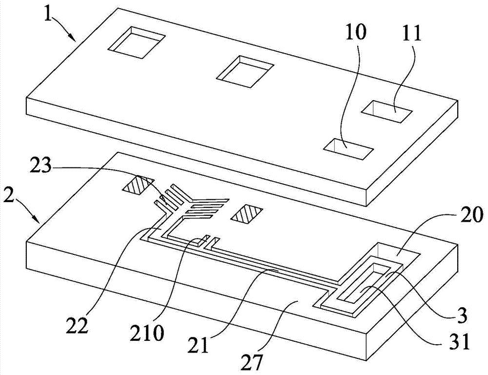
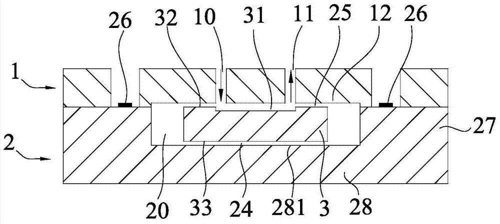
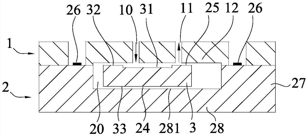
[0052] refer to Figure 1-3 , a MEMS microvalve, comprising a first silicon layer 1 and a second silicon layer 2, wherein a fluid inlet 10 and a fluid outlet 11 are opened on the first silicon layer 1, and a fluid inlet 10 and a fluid outlet 11 are formed on the second silicon layer 2 on the surface of the second silicon layer 2 The outer flow channel 20 and the rigid component 3 with the inner flow channel 31, the rigid component 3 is accommodated in the outer flow channel 20, and can move between the valve opening position and the valve closing position.

[0053] When designing the rigid component 3, this embodiment achieves a greater displacement output of the rigid component 3 through a special driving structure. Specifically: an actuating rib 23 and a transmission ridge are also provided in the outer flow channel 20 of the second silicon layer 2. 22 and the displacement amplifying beam 21, the actuating rib 23 is connected between the transmission ridge 22 and the side wa...

Embodiment 2

[0063] refer to Figure 5 , 6 , the microvalve of the present embodiment is also provided with a fluid pressure detection port 13 on its first silicon layer 1, and the fluid pressure detection port 13 is positioned between the fluid inlet 10 and the fluid outlet 11, thus, the microvalve can detect fluid inflow or Pressure at outflow.

[0064] Specifically: such as Figure 5 As shown, in the valve open state, the fluid inlet 10 communicates with the fluid pressure detection port 13, the fluid flows in from the fluid inlet 10, and flows out from the fluid pressure detection port 13. Within the response time, the fluid pressure detection port 13 obtains a standard fluid pressure signal, the microvalve works in boost mode.

[0065] Such as Figure 6 As shown, in the valve closed state, the fluid outlet 11 communicates with the fluid pressure detection port 13, the fluid flows out from the fluid outlet 11, the standard fluid pressure signal is released, and the microvalve works...

Embodiment 3

[0068] The present embodiment provides a kind of manufacturing technology of MEMS microvalve, comprises the following steps:

[0069] 1. Set the first silicon layer and the second silicon layer, wherein the material of the first silicon layer includes but not limited to (111), (100), (110) crystal silicon materials and other semiconductor materials, the second silicon The material of the layer is a single crystal silicon material with (111) crystal orientation;

[0070] 2. As shown in Figure 7(a), the inner flow channel 31 is etched on the upper surface of the second silicon layer 2;

[0071] 3. As shown in Figure 7(b), a mask 4 is partially deposited on the upper surface of the second silicon layer 2. In this step, the upper surface of the second silicon layer 2 is not completely covered with a mask, but the engraving of the subsequent process is reserved. Eclipse;

[0072] 4. As shown in Figure 7(c), the outer flow channel 20 is preliminarily etched on the upper surface of...


PUM


Abstract

The invention discloses a MEMS microvalve and its manufacturing process, relates to the MEMS technical field, and solves the technical problems of high requirements for the existing microvalve manufacturing process and poor pressure bearing capacity. The MEMS microvalve of the present invention includes a first silicon layer, composed of (111) crystal silicon material, and has a fluid inlet and a fluid outlet; the second silicon layer is made of (111) crystal silicon material, and has a fluid formed on the surface of the second silicon layer The outer flow channel and the rigid component with the inner flow channel, the rigid component is accommodated in the outer flow channel and can move between the valve opening position and the valve closing position, the second silicon layer includes a bonding part and a sealing part, and the second silicon layer The layer is bonded to the first silicon layer through the bonding part, the fluid inlet and the fluid outlet are located in the non-bonding area of ​​the first silicon layer, the outer flow channel is located between the non-bonding area of ​​the first silicon layer and the sealing part, and the upper part of the rigid part A buffer liquid gap is formed between the surface and the lower surface of the non-bonded region of the first silicon layer, and a suspension liquid gap is formed between the lower surface of the rigid component and the inner wall surface of the sealing part.

Description

[0001] 【Technical field】 [0002] The invention relates to a MEMS (micro-electro-mechanical system) microvalve and a manufacturing process thereof, in particular to a microvalve based on MEMS technology, and belongs to the technical field of MEMS. [0003] 【Background technique】 [0004] MEMS (Micro-Electro-Mechanic System, Micro-Electro-Mechanical System) refers to a micro-device or micro-device that can be mass-produced and integrates micro-mechanisms, micro-sensors, micro-actuators, signal processing and control circuits, until interfaces, communications and power supplies are integrated. system. Microsensors, microactuators, microcomponents, micromechanical optical devices, and microfluidic devices made by MEMS technology have very broad application prospects in aerospace, consumer electronics, military and other fields, and are also widely used in microfluidics. chips and synthetic biology. [0005] As a key device for fluid control, silicon microvalve has outstanding ap...

Claims


Application Information

Patent Timeline
Patent Type & Authority Patents(China)
IPC IPC(8): B81B3/00B81C1/00
Inventor 段飞张胜昌
Owner ZHEJIANG DUNAN ARTIFICIAL ENVIRONMENT
Learn More