Non-aqueous decarburization solution for capturing carbon dioxide in mixed gas and application thereof

A carbon dioxide and mixed gas technology, which is applied in air quality improvement, chemical instruments and methods, and dispersed particle separation, can solve the problems of low decarbonization capacity and high regeneration energy consumption, and achieve low regeneration energy consumption, fast mass transfer, and high viscosity small effect

Active Publication Date: 2015-04-08
DALIAN UNIV OF TECH
View PDF14 Cites 17 Cited by
  • Summary
  • Abstract
  • Description
  • Claims
  • Application Information

AI Technical Summary

Problems solved by technology

[0014] The purpose of the present invention is to develop a non-aqueous decarburization solution that captures carbon dioxide in a mixed gas to solve the above problems of low decarburiz

Method used


Image

  • Non-aqueous decarburization solution for capturing carbon dioxide in mixed gas and application thereof
  • Non-aqueous decarburization solution for capturing carbon dioxide in mixed gas and application thereof
  • Non-aqueous decarburization solution for capturing carbon dioxide in mixed gas and application thereof

Examples


Embodiment 1

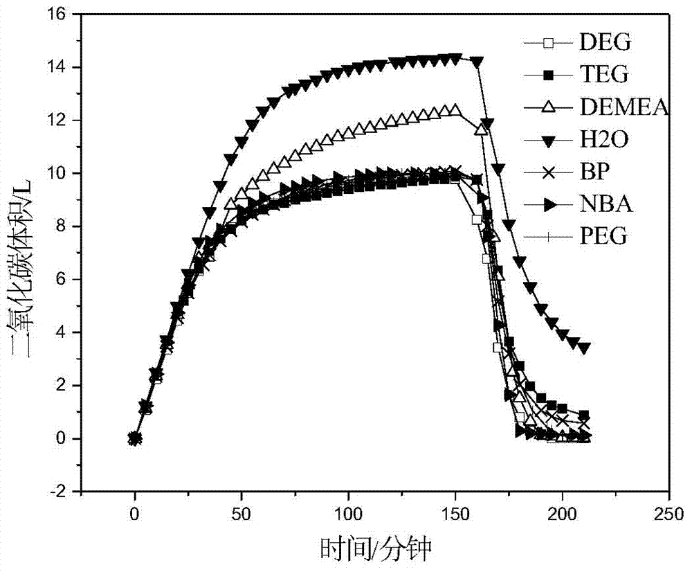
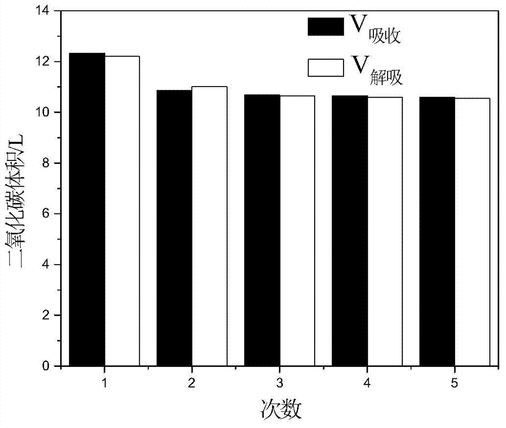
[0047] With 200g non-aqueous decarburization solution as absorption solution, pack in the reactor that is furnished with constant temperature oil bath stirrer of 500ml (experimental apparatus sees Figure 5 ), wherein the mass fraction of EMEA is 40%, and DEMEA is as a solvent, and its mass fraction is 60%. At a temperature of 40°C, at a flow rate of 250ml / min, CO with a pressure of 0.2MPa and a concentration of 99.995% was introduced. 2 , Use a wet anti-corrosion flowmeter for continuous measurement, and thus calculate the absorption rate and amount of carbon dioxide. After the solution reaches saturation, set the temperature of the oil bath to 120°C for desorption, and measure the desorption amount and desorption rate for 60 minutes. After five absorption and desorption tests, check its stability (see figure 1 and 3 ).

Embodiment 2

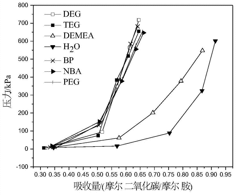
[0049] 200g of non-aqueous decarburization solution is used as the absorption solution, and the filling volume is 1105cm 3 Vacuum the stainless steel reactor. Another gas storage tank has a volume of 1290cm 3 , the reactor and the storage tank are all placed in a water bath to keep the temperature at 40°C, and the equilibrium temperature and pressure in the reactor and storage tank are measured by a K-type thermocouple and a pressure sensor (for the experimental device, see Figure 6 ).

[0050] As can be seen from the examples, in the case of non-water, the solution absorption decreases slightly, but the desorption rate is fast. When the saturated carbon dioxide absorption solution is desorbed at 120 ° C, the desorption rate decreases with the increase of the reaction time. Moreover, after five times of absorption and desorption, the absorption and desorption amounts are similar and stable, and can be applied industrially.

[0051] In summary, the non-aqueous decarburizati...


PUM


Abstract

The invention provides non-aqueous decarburization solution for capturing carbon dioxide in a mixed gas, and belongs to the technical field of capturing of carbon dioxide gas. The invention relates to a non-aqueous decarburization solution, wherein a main absorption component is N-ethyldiethanolamine, and a solvent is N,N-diethylethanolamine. Because the non-aqueous decarburization solution has a high boiling point and low viscosity, uses tertiary amine capable of participating in CO2 absorption as the solvent, and uses secondary amine with a fast absorption speed and a high absorption amount, and easy to regenerate as the main absorption solvent, the absorption capacity, purification degree and desorption speed for carbon dioxide are increased, the temperature range of the reaction is expanded, the volume of a regeneration tower is reduced, the energy consumption of the regeneration is greatly reduced, and the equipment investment and operation cost are reduced. The non-aqueous decarburization solution provided by the invention is mainly used for capturing carbon dioxide in the tail gases of multiple chemical reactions, the tail gases of steel plants and cement plants, ore decomposition gas, combustion flue gas, natural gas, city gas and marsh gas, and has wide application prospect.

Description

technical field [0001] The invention belongs to the technical field of gas separation, and relates to a non-aqueous decarburization solution for capturing carbon dioxide in mixed gas and an application thereof. Background technique [0002] It is well known that CO produced by human activities 2 Nearly 1 / 3 of that comes from the burning of fossil fuels. Different industrial production sectors emit large amounts of CO 2 , such as: refineries, cement plants, ironworks, power plants, lime plants, magnesia plants, etc. CO 2 Excessive emissions will cause atmospheric CO 2 The concentration of the pollutants reaches a high level, which will bring a series of environmental problems, and this phenomenon has caused widespread public and political concern. capture and store CO 2 ways to reduce atmospheric CO 2 content. [0003] Existing technologies for separation and recovery of carbon dioxide include: physical methods, chemical methods, and biological methods. Physical meth...

Claims


Application Information

Patent Timeline
IPC IPC(8): B01D53/14
CPCY02A50/20Y02C20/40
Inventor 张永春陈思铭陈绍云秦梁
Owner DALIAN UNIV OF TECH
Why Eureka
Try Eureka