Novel method for slotting front grid line electrode of crystalline silicon solar battery and manufacturing method of solar battery

A technology of solar cells and manufacturing methods, applied in the direction of final product manufacturing, sustainable manufacturing/processing, circuits, etc., can solve the problems of poor contact, large shadow loss, and high cost, so as to reduce shadow loss, reduce production costs, reduce The effect of reflectivity

Inactive Publication Date: 2015-04-29
YUNNAN UNIV
View PDF6 Cites 4 Cited by
  • Summary
  • Abstract
  • Description
  • Claims
  • Application Information

AI Technical Summary

Problems solved by technology

However, the screen printing technology has the following defects: 1. There is a layer of non-conductive glass between the sintered silver grid electrode and silicon, and the contact resistance is very large; 2. The organic matter in the silver paste evaporates during the sintering process, making the silver electrode It is loose and porous, and the volume resistance of silver electrodes is large; 3. The grid lines of screen printing are generally larger than 80 μm, and it is difficult to reduce the line width, and one printing can only produce a line height of less than 25 μm. It will cause the grid line to be further widened, so the aspect ratio is small, and the wider line width reduces the effective working area of ​​the solar cell, so the shadow loss is large; 4. The silver material itself is expensive
Using lithographic slotting requires photolithography, chemical directional etching or mechanical etching slotting to provide a mask for electroplating, chemical plating or light-induced electroplating, although it solves the problem of large contact resistance and bulk in screen printing. The shortcomings of large resistance and large shadow loss, but the process is too complicated, the production cost is too high, and the equipment production efficiency is low, so it has not been widely used in the industry.
[0005]In short, the existing solar cell production technology is difficult to overcome the shortcomings of large contact resistance, large volume resistance, large shadow loss, high cost, and complicated production process. The substrate only relies on high-temperature sintering to form an insulating glass body to maintain contact. Under vibration or long-term exposure to sunlight, due to lattice mismatch, it is easy to cause metal grid lines to delaminate and cause poor contact, which affects the capture of photogenerated electrons and affects the conversion efficiency of solar cells.

Method used

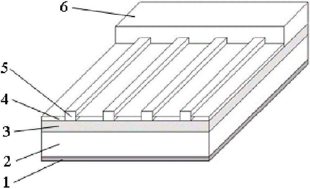
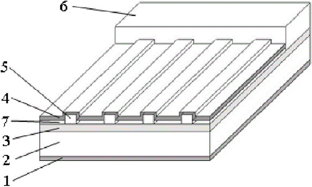
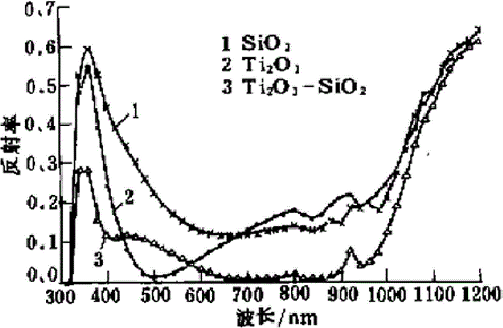

Image

  • Novel method for slotting front grid line electrode of crystalline silicon solar battery and manufacturing method of solar battery
  • Novel method for slotting front grid line electrode of crystalline silicon solar battery and manufacturing method of solar battery
  • Novel method for slotting front grid line electrode of crystalline silicon solar battery and manufacturing method of solar battery

Examples


Embodiment 1

[0108] Example 1 : prepare the electrolytic solution for light induction, the electrolytic solution is a plating solution containing 0.01mol / L of Co metal ions, which is filled in the electrolytic cell. Place the N region of the solar cell after cleaning the texture, diffusing to make the P-N junction, etching and dephosphorizing, and making the back electrode in the electrolyte, and connect the back electrode surface and the counter electrode placed in the electrolyte with wires, to form a closed loop. Slots are made in the N area of ​​the solar cell, and the light emitted by the fluorescent lamp is irradiated on the N area of ​​the solar cell to form a grid line shape. Metal ions are reduced to metal deposits in the illuminated area. At the same time, the photogenerated holes are transported along the wire to the counter electrode to dissolve the metal into metal ions to supplement the loss of ions in the solution, so the reaction continues until the electric quantity mea...

Embodiment 2

[0109] Example 2: The electrolytic solution used for light induction is prepared, and the electrolytic solution is a plating solution containing 1mol / L of Ni metal ions, which is filled in the electrolytic cell. Place the N region of the solar cell after cleaning the texture, diffusing to make the P-N junction, etching and dephosphorizing, and making the back electrode in the electrolyte, and connect the back electrode surface and the counter electrode placed in the electrolyte with wires, to form a closed loop. Slots are made in the N area of ​​the solar cell, and the light emitted by the fluorescent lamp is irradiated on the N area of ​​the solar cell to form a grid line shape. Metal ions are reduced to metal deposits in the illuminated area. At the same time, the photogenerated holes are transported along the wire to the counter electrode to dissolve the metal into metal ions to supplement the loss of ions in the solution, so the reaction continues until the electric qua...

Embodiment 3

[0110] Example 3 : preparation is used for the electrolytic solution of light induction, and described electrolytic solution is the plating solution that contains the Co metal ion of 0.3mol / L, and it is filled in the electrolytic cell. Place the N region of the solar cell after cleaning the texture, diffusing to make the P-N junction, etching and dephosphorizing, and making the back electrode in the electrolyte, and connect the back electrode surface and the counter electrode placed in the electrolyte with wires, to form a closed loop. Slots are made in the N area of ​​the solar cell, and the light emitted by the fluorescent lamp is irradiated on the N area of ​​the solar cell to form a grid line shape. Metal ions are reduced to metal deposits in the illuminated area. At the same time, the photogenerated holes are transported along the wire to the counter electrode to dissolve the metal into metal ions to supplement the loss of ions in the solution, so the reaction continue...


PUM


Abstract

The invention discloses a novel method for slotting a front grid line electrode of a crystalline silicon solar battery and a manufacturing method of the solar battery. The crystalline silicon solar battery comprises a crystalline silicon P-N knot substrate, a back electrode, a front grid electrode and a reflection reduction layer, wherein the front grid electrode is in ohmic contact with the N zone of the crystalline silicon P-N knot substrate; the reflection reduction layer is positioned on the surface of the N zone of the crystalline silicon P-N knot substrate. The manufacturing method comprises the following steps: washing and texturing, diffusing, manufacturing knots, washing phosphorus, etching, preparing the back electrode, performing silk-screen printing on a front grid line electrode model, preparing the reflection reduction layer, oxidizing and sintering, and electroplating the front grid line electrode. With the combination of a conventional silk-screen printing technique, an emitter electrode can be slotted, the front grid electrode can be electroplated, oxidized and sintered in a photoinduction manner, and the novel method is convenient to combine with industrial production and has the characteristics of simple production process, high efficiency and high photoelectric conversion efficiency.

Description

Technical field [0001] The present invention involves a new crystal silicon solar cell front grid wire groove method and the manufacturing method of the solar cell, especially a high -conversion efficiency crystal silicon solar cell and its manufacturing method.The field of solar technology. Background technique [0002] In 1839, French scientist BECQUEREL found that light can cause potential differences between different parts of semiconductor materials.That is "photovoltaic effect".In 1954, American scientists Chabin and Pilson first made a practical monocrystalline silicon solar cell in Bell Labs in the United States, which was born with practical photovoltaic power generation technology that converts solar light into electrical energy.After more than half a century of technology improvement, crystalline silicon solar batteries are still 80-90%of solar power generation.However, improving the conversion efficiency of crystal silicon solar cells, reducing costs has always been t...

Claims


Application Information

Patent Timeline
Patent Type & Authority Applications(China)
IPC IPC(8): H01L31/18H01L31/0224
CPCH01L31/02168H01L31/022425H01L31/068H01L31/1804Y02E10/546Y02E10/547Y02P70/50
Inventor 刘铸李俊杰申皓罗晓斌李璇何桃玲
Owner YUNNAN UNIV
Why Eureka
Try Eureka