

Low-rank coal adiabatic pyrolysis device
A low-rank coal and thermal insulation technology, which is applied in the direction of direct heating dry distillation, special form dry distillation, petroleum industry, etc., can solve the problems of high strength requirements of reactor materials, easy wear and tear, difficult maintenance and other problems, and achieve easy control of residence time and increase heat High solution efficiency and good heat insulation effect
- Summary
- Abstract
- Description
- Claims
- Application Information
AI Technical Summary
Problems solved by technology
Method used
Image

Examples
specific Embodiment approach
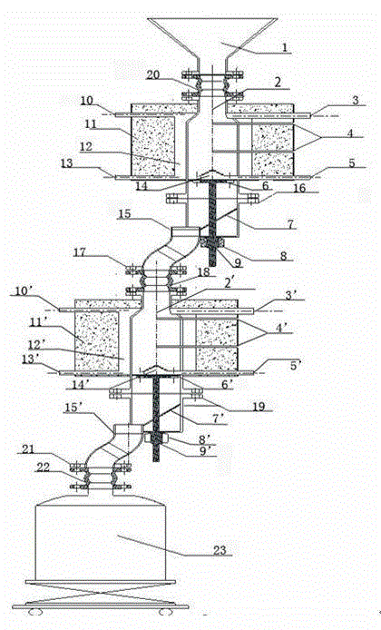
[0039] To implement a low-rank coal adiabatic pyrolysis device, a gas insulation layer and an outer insulation layer are sequentially arranged around the retort chamber, and when the low-rank coal is adiabatically pyrolyzed, the gas is injected into the gas insulation chamber layer to react with the pyrolysis reaction. The isothermal heat-carrying temperature gas makes the wall temperature of the reaction device basically consistent with the central reaction temperature of the reaction device, and the gas insulation layer does not exchange heat with the drying chamber / distillation chamber to avoid heat loss reduction. The specific improvement measures taken are to coaxially install a gas insulation layer jacket around the outer wall of the retort, and set up a hot gas circulation pipeline, so that the heated gas enters from the insulation gas inlet and the high temperature gas inlet of the adiabatic reaction device respectively, and the high temperature The heat-carrying gas ex...
specific Embodiment approach 2
[0049] This specific embodiment 2 is an embodiment based on the specific embodiment 1, and those skilled in the art can realize the technical solution of the present invention according to the following specific embodiments.
[0050] as attached figure 1 , N 2 After heating up to 600°C with a 30kw heater, the high-temperature gas inlet and the insulating gas inlet of the adiabatic retort chamber are fed into, and the temperature of the air inlet of the adiabatic retort chamber and the temperature of the central area are compared with time as shown in the appendix Image 6 , It can be observed from the attached figure that the basic heat loss is within the acceptable range≦30°C without adding coal material, which ensures the thermal insulation effect of the device.
[0051] as attached figure 1 , 3 kg of lignite with a particle size of 1 to 5 mm, relying on gravity, enters the reaction device from the hopper, N 2 After the 15KW heater is heated to about 300°C, it is passed i...
specific Embodiment approach 3
[0053] On the basis of Embodiment 1, by changing the particle size of coal, observe its reaction.
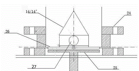
[0054] Put 3.0kg lignite with a particle size of 5-10mm into the reaction device from the hopper by gravity, N 2 After the 15KW heater is heated to about 300°C, it is passed into the gas insulation layer and the heat-insulating drying room respectively, and the coal material in the heat-insulating drying room is preheated and dried. The drying time is about 20 minutes; then the coal material passes through the discharge hole on the discharge turntable. Falling into the chute, the coal is controlled by the high temperature ball valve to enter the adiabatic retort chamber; N 2 After a 30kw heater heats up to 600°C, it enters from the gas distributor at the bottom of the adiabatic retort chamber and exchanges heat with the coal material. After a period of time, the temperature of the coal material rises and begins to pyrolyze, releasing pyrolysis volatiles. Get half-focused. The ...
PUM
| Property | Measurement | Unit |
|---|---|---|
| Diameter | aaaaa | aaaaa |
| Diameter | aaaaa | aaaaa |
| Diameter | aaaaa | aaaaa |
Abstract
Description
Claims
Application Information