Low-cost coal-fired flue gas various pollutant ultralow emission system and low-cost coal-fired flue gas various pollutant ultralow emission method

A technology for coal-fired flue gas and emission systems, which is applied in combustion methods, separation methods, chemical instruments and methods, etc., can solve the problems of inapplicability, high investment, high cost, and high renovation costs in areas where water resources are scarce, so as to reduce liquid Drop carrying, prevent equipment corrosion, and ensure the effect of uniform water film distribution

Inactive Publication Date: 2015-07-08
ZHEJIANG UNIV
View PDF6 Cites 17 Cited by
  • Summary
  • Abstract
  • Description
  • Claims
  • Application Information

AI Technical Summary

Problems solved by technology

[0008] Domestic and foreign patents on the integration of desulfurization, denitrification and dust removal technology are also mentioned. The technical route adopted is mainly low-nitrogen combustion + selective catalytic reduction + electrostatic precipitator + wet desulfurization + wet electrostatic precipitator. This technical route can achieve ultra-low emission effect, but the investment and cost are high. There are problems in the transformation of the current semi-dry flue gas desulfurization system, and the water consumption of this route is large, and the transformation cost is high. It is not suitable for areas with scarce water resources.

Method used


Image

  • Low-cost coal-fired flue gas various pollutant ultralow emission system and low-cost coal-fired flue gas various pollutant ultralow emission method
  • Low-cost coal-fired flue gas various pollutant ultralow emission system and low-cost coal-fired flue gas various pollutant ultralow emission method

Examples


Embodiment 1

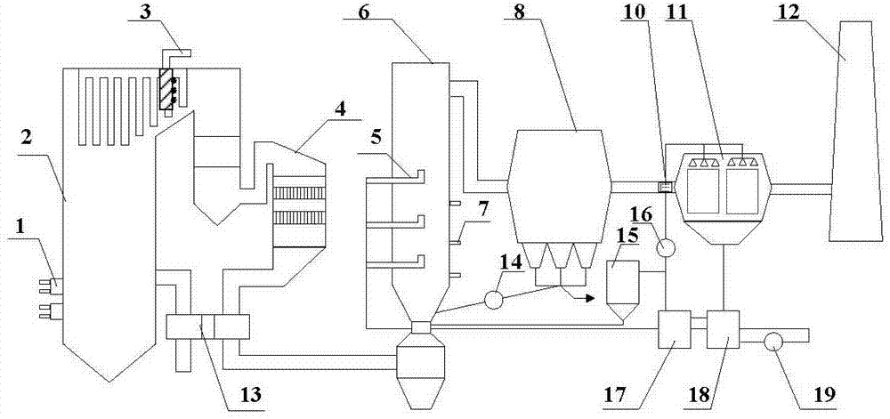
[0047] refer to figure 1 , a low-cost coal-fired flue gas multi-pollutant ultra-low emission system, the emission system includes a nitrogen oxide cascade control system, a semi-dry flue gas purification system and a wet electrostatic deep purification system in series,

[0048] The nitrogen oxide cascade control system includes a sequentially connected low-nitrogen burner 1, a selective non-catalytic reduction denitrification device 3 and a selective catalytic reduction denitrification device 4, and the low-nitrogen burner 1 is arranged in the boiler 2. The non-catalytic reduction denitrification device 3 is arranged on the top of the boiler 2;

[0049] The semi-dry flue gas purification system includes an absorption tower 6, a bag filter 8, a feeding device 14 and a lime digestion device 15, the bag filter 8 is connected to the absorption tower 6 through the feeding device 14, and the lime digestion device 15 communicates with the absorption tower 6; the absorption tower 6 ...

Embodiment 2

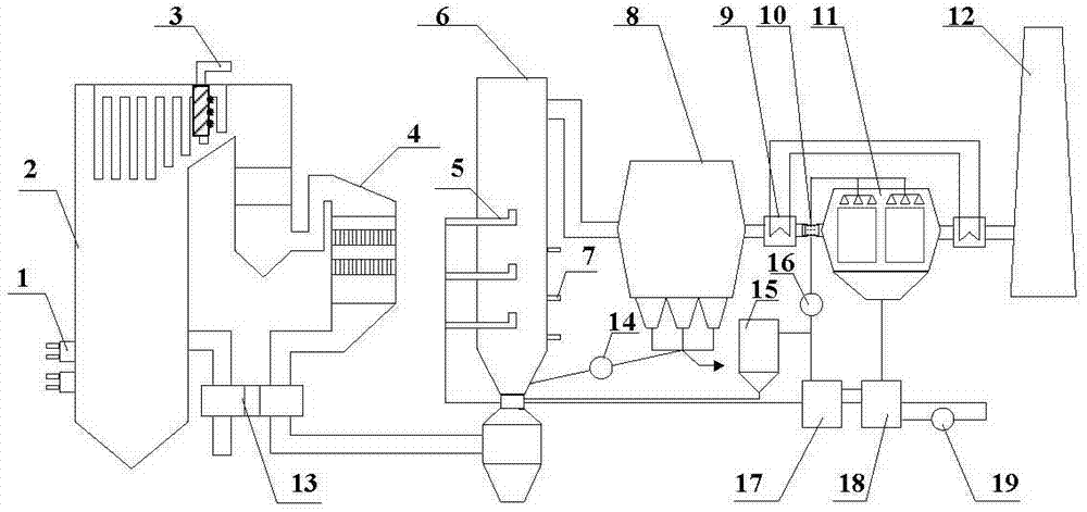
[0054] refer to figure 2 , a low-cost coal-fired flue gas multi-pollutant ultra-low emission system, the emission system includes a nitrogen oxide cascade control system, a semi-dry flue gas purification system and a wet electrostatic deep purification system in series,

[0055] The nitrogen oxide cascade control system includes a sequentially connected low-nitrogen burner 1, a selective non-catalytic reduction denitrification device 3 and a selective catalytic reduction denitrification device 4, and the low-nitrogen burner 1 is arranged in the boiler 2. The non-catalytic reduction denitrification device 3 is arranged on the top of the boiler 2;

[0056] The semi-dry flue gas purification system includes an absorption tower 6, a bag filter 8, a feeding device 14 and a lime digestion device 15, the bag filter 8 is connected to the absorption tower 6 through the feeding device 14, and the lime digestion device 15 communicates with the absorption tower 6; the absorption tower 6...

Embodiment 3

[0061] refer to figure 1 , a method for ultra-low emission of various pollutants in low-cost coal-fired flue gas, comprising the following steps:

[0062] (1) Air and pulverized coal enter the low-nitrogen burner 1 for preliminary control of the concentration of nitrogen oxides. After the treatment by the low-nitrogen burner 1, the concentration of nitrogen oxides in the flue gas at the furnace outlet is lower than 200mg / m 3 Then enter the selective non-catalytic reduction denitrification device 3 to reduce the concentration of nitrogen oxides successively. The selective non-catalytic reduction denitrification device 3 injects a reducing agent into the area where the furnace temperature is 850-1100 ° C, and the nitrogen oxides in the flue gas N 2 and water, and the excess ammonia participates in the denitrification reaction of the selective catalytic reduction denitrification device 4; Reduced to 50mg / m 3 the following;

[0063] (2) The flue gas after passing through the s...


PUM

PropertyMeasurementUnit
denitrification rateaaaaaaaaaa

Abstract

The invention relates to a low-cost coal-fired flue gas various pollutant ultralow emission system and a low-cost coal-fired flue gas various pollutant ultralow emission method. The system mainly includes a nitrogen oxide gradient control system, a semidry flue gas purifying system and a wet-type static deep purification system. In the invention, by means of the nitrogen oxide gradient control system, the emitted NOx is less than 50 mg/Nm3 in concentration; by means of the semidry flue gas purifying system, the removal efficiency of SO2 can be reach not less than 90%, the removal efficiency of SO3 can be reach not less than 90%, the removal efficiency of acidic gas can be reach not less than 95% and the dust is less than 30 mg/Nm3; and by means of the wet-type static deep purification system, the PM is less than 5 mg/Nm3 and the removal efficiency of SO2 can be reach not less than 50%. The dust-containing waste water in the wet-type static deep purification system is used for slaking limestone and moistening and activating an absorbent in the semidry flue gas purifying system, so that near-zero emission of the waste water in the system is achieved and finally it is achieved that the pollutant emission concentrations of PM is less than 5 mg/Nm3, the emission concentration of SO2 is less than 35 mg/Nm3 and the emission concentration of SO2 is less than 50 mg/Nm3 in a coal-fired power plant, thereby achieving an ultralow emission requirement of the main pollutant under a condition of the near-zero emission of the waste water.

Description

technical field [0001] The invention belongs to the technical field of coal-burning flue gas pollutant control, and in particular relates to a low-cost coal-burning flue gas multi-pollutant ultra-low emission system and method. Background technique [0002] In recent years, vast areas of our country have successively fallen into severe and persistent smog and polluted weather, which has attracted widespread attention from the news media and public opinion. PM forming smog 2.5 In addition to fine particles (primary particles) directly emitted by pollution sources, particles also include SO 2 , NO X Fine particles (secondary particles) generated by photochemical action. [0003] Coal burning is one of the main causes of air pollution. In 2013, my country's total coal consumption was 3.61 billion tons, of which thermal power generation accounted for about 50%. In 2012, my country's thermal power generation consumed 1.79 billion tons of coal and emitted a total of SO 2 8....

Claims


Application Information

Patent Timeline
Patent Type & Authority Applications(China)
IPC IPC(8): B01D53/75B01D53/79B01D53/90B01D53/80B01D53/56B01D53/50B01D53/68B01D53/64B01D50/00F23C5/08F23J15/02F23J15/04F23J15/00F23L15/00
CPCY02E20/34
Inventor 高翔郑成航骆仲泱岑可法倪明江张涌新王毅杨正大施正伦周劲松方梦祥程乐鸣王勤辉
Owner ZHEJIANG UNIV
Why Eureka
Try Eureka