Supercharge Your Innovation With Domain-Expert AI Agents!

A Harmless Treatment Process and System for Drilling Solid Waste

A harmless treatment and drilling technology, applied in sludge treatment, pyrolysis treatment sludge, solid waste removal, etc.

Active Publication Date: 2016-06-15
陆骏
View PDF6 Cites 0 Cited by
  • Summary
  • Abstract
  • Description
  • Claims
  • Application Information

AI Technical Summary

Problems solved by technology

[0012] The technical problem to be solved by the present invention is to provide a treatment effect that can treat sewage and sludge in a harmless manner and achieve complete volume reduction, harmlessness and resource utilization in view of the above-mentioned defects of the prior art. It can avoid the problem of sludge agglomeration and clogging in the atomized high-temperature pyrolysis tower, high treatment efficiency, better treatment effect, lower energy consumption, high recovery and reuse rate of barite powder, etc., small footprint, low investment and operation Low-cost, safe and environmentally friendly drilling solid waste harmless treatment process and treatment system

Method used


Image

  • A Harmless Treatment Process and System for Drilling Solid Waste
  • A Harmless Treatment Process and System for Drilling Solid Waste

Examples


Embodiment 1

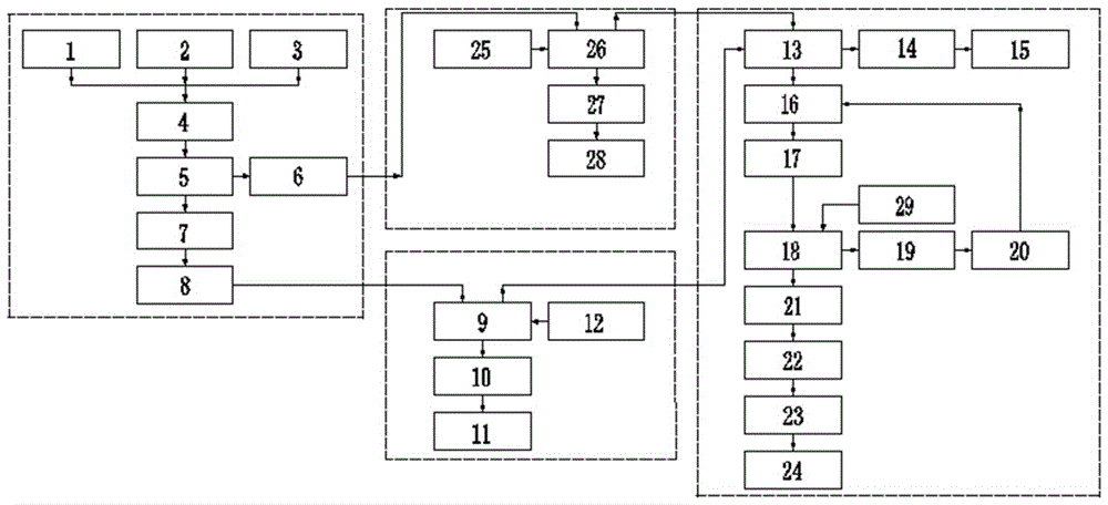
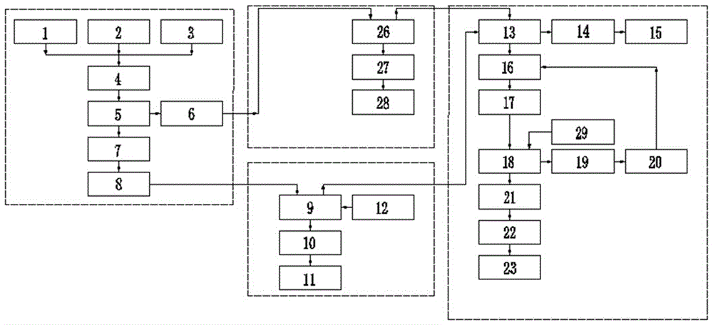
[0064] This embodiment provides a harmless treatment process for drilling solid waste, such as figure 1 shown, including the following steps:

[0065] (a) Screening and separation of sludge particles: the debris sludge produced by the vibrating screen 1, the desilter 2 and the centrifuge 3 is transported to the solid-liquid screening mechanism 5 through the sludge auger conveying device 4 for a long distance. Solid-liquid sieving to obtain rock debris solid waste coarse particles with a particle size greater than 40 mesh and sludge slurry with a particle size less than 40 mesh, and transport the rock debris solid waste coarse particles to the rock debris solid waste bin 6 for processing, and the sludge The mud is transported through the mud tank 7 to the pressure-supply slurry delivery mechanism 8 for processing;

[0066] Wherein, after the sludge slurry is stored in the slurry tank 7, the sludge slurry in the slurry tank 7 is stirred by using a mechanical agitator and an air...

Embodiment 2

[0074] This embodiment provides a treatment system for the harmless treatment process of drilling solid waste in the first embodiment, such as figure 2 As shown, including sludge non-falling slurry supply assembly, cuttings particle high temperature pyrolysis assembly, mud high temperature pyrolysis assembly and toxic and harmful gas treatment assembly;

[0075] The sludge non-falling slurry supply assembly includes the above-mentioned vibrating screen 1, sand and desilter 2, centrifuge 3, sludge auger conveying device 4, solid-liquid screening mechanism 5, cuttings and solid waste bin 6 and pressure The slurry feeding conveying mechanism 8, and the outlet of the sludge auger conveying device 4 communicates with the inlet of the solid-liquid screening mechanism 5, and the inlet of the cuttings solid waste bin 6 communicates with the inlet of the solid-liquid screening The first discharge port of the mechanism 5 is connected, and a mud tank 7 is arranged between the feed port ...


PUM

PropertyMeasurementUnit
particle sizeaaaaaaaaaa
solid contentaaaaaaaaaa

Abstract

The invention discloses a well-drilling solid waste harmless treatment technology and system. The technology comprises a, sludge particle screening separation, b, rock debris solid waste coarse grain treatment, c, dirty slurry high temperature pyrolysis, d, fine dust-containing poisonous and harmful exhaust-gas treatment, e, secondary high temperature burning pyrolysis treatment, f, spray quenching treatment and g, ultrafine dust particle exhaust-gas treatment. The well-drilling solid waste harmless treatment technology and system realize synchronous harmless treatment on sewage and sludge, realize thorough volume reduction, harmlessness and recycling treatment effects, prevent sludge caking blocking in an atomization high temperature pyrolysis tower, have high treatment efficiency, good treatment effects and low energy consumption, realize high barite powder recovery and utilization rate, has a small land occupation area and a low investment and operation cost, and is safe and environmentally friendly.

Description

technical field [0001] The invention relates to the field of oil drilling water-based sludge treatment, in particular to a process and system for harmless treatment of drilling solid waste. Background technique [0002] Drilling solid waste is a multiphase stable colloidal suspension system produced during petroleum exploration and development, including clay, weighted materials, various chemical treatment agents, sewage, dirty oil, and cuttings. [0003] Petroleum drilling solid waste sludge is a kind of chemical composition waste mud with no calorific value, which contains natural soluble salts, barite powder, bentonite and other solid particles, suspended matter, polyacrylamide, sulfonated asphalt, hydrogen sulfide, Microorganisms, colloids, bacteria, germs, cysts, toxic and harmful pollutants, etc., as well as chemical additives such as acids, oxygen scavengers, lubricants, bactericides, and scale inhibitors injected into the formation. At present, the methods of sludge...

Claims


Application Information

Patent Timeline
Patent Type & Authority Patents(China)
IPC IPC(8): C02F11/00C02F11/10F23G7/06B01D50/00B09B3/00B09B5/00
CPCY02W10/40
Inventor 陆骏尹晓伟
Owner 陆骏
Features
  • R&D
  • Intellectual Property
  • Life Sciences
  • Materials
  • Tech Scout
  • Unparalleled Data Quality
  • Higher Quality Content
  • 60% Fewer Hallucinations
Learn More