Organic electroluminescence device

An electroluminescent device and electroluminescent technology, applied in the direction of organic semiconductor devices, electro-solid devices, electrical components, etc., can solve the problems of low light emitting performance, refractive index difference, light loss, etc., to improve luminous efficiency, hole transport, etc. The effect of enhanced performance and enhanced light extraction efficiency

Active Publication Date: 2016-05-11
宿州市徽腾知识产权咨询有限公司
View PDF4 Cites 2 Cited by
  • Summary
  • Abstract
  • Description
  • Claims
  • Application Information

AI Technical Summary

Problems solved by technology

Since the material of the existing hole injection layer is usually a metal oxide, its light absorption rate in the visible light range is high, resulting in light loss; in addition, the metal oxide is an inorganic substance, which is different from the organic material of the hole transport layer. Larger, there is a difference in refractive index between the two interfaces, which is easy to cause total reflection, resulting in lower overall light output performance of OLED

Method used


Image

  • Organic electroluminescence device
  • Organic electroluminescence device

Examples


Embodiment 1

[0048] A method for preparing an organic electroluminescent device, comprising the following steps:

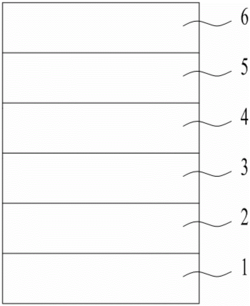
[0049] (1) The conductive anode 1 is made of indium tin oxide glass (ITO). First, the conductive anode 1 is subjected to photolithography treatment, and then cut into 2×2cm 2 Then use detergent, deionized water, acetone, ethanol, and isopropanol to ultrasonically clean the glass surface for 15 minutes to remove organic pollutants on the glass surface, clean it and air dry it;

[0050] (2) 20mgMoO 3 Immerse in 10ml of zinc acetate solution, the mass percentage concentration of zinc acetate solution is 35%, soak for 60min to obtain a suspension solution, after drying the suspension solution, put it in a muffle furnace for calcination, the calcination temperature is 400°C, and the calcination time is 30min, to obtain MoO coated with ZnO particles on the surface 3 , and then use the vacuum coating system to 5×10 -3 The pressure of Pa and the evaporation rate of 1nm / s will coat ...

Embodiment 2

[0059] A method for preparing an organic electroluminescent device, comprising the following steps:

[0060] (1) The conductive anode is made of aluminum-doped zinc oxide glass (AZO). First, the conductive anode is subjected to photolithography treatment, and then cut into 2×2cm 2 Then use detergent, deionized water, acetone, ethanol, and isopropanol to ultrasonically clean the glass surface for 15 minutes to remove organic pollutants on the glass surface, clean it and air dry it;

[0061] (2) 50mgWO 3 Soak in 10ml of zinc acetate solution, the mass percent concentration of zinc acetate solution is 10%, soak for 30min to obtain a suspension solution, dry the suspension solution, put it in a muffle furnace for calcination, the calcination temperature is 500°C, and the calcination time is 15min to obtain WO coated with ZnO particles on the surface 3 , the mass ratio of zinc acetate to tungsten oxide is 0.02:1, and then the vacuum coating system is used to 2×10 -4 The pressure...

Embodiment 3

[0070] A method for preparing an organic electroluminescent device, comprising the following steps:

[0071] (1) The conductive anode is made of indium-doped zinc oxide glass (IZO). First, the conductive anode is photolithographically processed, and then cut into 2×2cm 2 Then use detergent, deionized water, acetone, ethanol, and isopropanol to ultrasonically clean the glass surface for 15 minutes to remove organic pollutants on the glass surface, clean it and air dry it;

[0072] (2) Add 10mgV 2 o 5 Immerse in 10ml of zinc acetate solution, the mass percentage concentration of zinc acetate solution is 60%, soak for 60min to obtain a suspension solution, after drying the suspension solution, put it in a muffle furnace for calcination, the calcination temperature is 300°C, and the calcination time is 60min, to obtain the surface coated with ZnO particles V 2 o 5 , the mass ratio of zinc acetate to vanadium pentoxide is 0.6:1, and then the vacuum coating system is used to 1×1...


PUM


Abstract

The invention discloses an organic electroluminescence device which comprises a conductive anode, a hole doping layer, a luminescence layer, an electron transport layer, an electron injection layer and a cathode which are sequentially laminated, wherein the material of the hole doping layer is a metal oxide coated with zinc oxide particles on the surface. The invention also discloses a preparation method of the organic electroluminescence device. According to the invention, the hole doping layer has hole injection ability as well as hole transport ability, the hole-electron combination probability can be effectively improved, and the luminous efficiency of the organic electroluminescence device is improved.

Description

technical field [0001] The invention relates to the field of organic electroluminescence, in particular to an organic electroluminescence device. Background technique [0002] In 1987, C.W.Tang and Van Slyke of EastmanKodak Company in the United States prepared a high-brightness, high-efficiency double-layer organic electroluminescent device (OLED) using ultra-thin film technology. The principle of OLED light emission is based on the action of an external electric field, electrons are injected from the cathode to the lowest unoccupied molecular orbital (LUMO) of organic matter, and holes are injected from the anode to the highest occupied orbital (HOMO) of organic matter. Electrons and holes meet, recombine, and form excitons in the light-emitting layer. Excitons migrate under the action of an electric field, transfer energy to the light-emitting material, and excite electrons to transition from the ground state to the excited state. The excited state energy is deactivated b...

Claims


Application Information

Patent Timeline
Patent Type & Authority Applications(China)
IPC IPC(8): H01L51/50H01L51/52H01L51/54H01L51/56
CPCH10K85/30H10K50/155H10K50/17H10K50/15H10K50/854H10K2102/00H10K2102/331H10K71/00
Inventor 不公告发明人
Owner 宿州市徽腾知识产权咨询有限公司
Why Eureka
Try Eureka