Modified diaphragm and preparation method and application therefor

A diaphragm and modification technology, which is applied in the field of double-sided modified modified diaphragm and its preparation, can solve the problems of cycle life and rate performance of modified diaphragm lithium-sulfur batteries, weak alumina adsorption capacity, pierced diaphragm, etc. problem, to achieve the effect of inhibiting the shuttling effect, inhibiting the growth, and preventing the puncture of the septum

Inactive Publication Date: 2016-06-15
CENT SOUTH UNIV
View PDF4 Cites 55 Cited by
  • Summary
  • Abstract
  • Description
  • Claims
  • Application Information

AI Technical Summary

Problems solved by technology

In terms of diaphragm modification, porous carbon nanotube / polyethylene glycol modified diaphragm [GuanchaoWang, Royal Society of Chemistry A, 2015, 3, 7139], carbon modified diaphragm [Shengheng Chung, AdvFunctMater, 2014, 24, 5299-5306] and other functional diaphragms The application of lithium-sulfur batteries improves the cycle life and rate performance of lithium-sulfur batteries. However, the carbon material is coated on the separator. Due to the pore structure of the separator and the electronic conductivity of the carbon material, it is easy to cause a short circuit after assembling the battery. Feasible measures were proposed for negative electrode protection. The application of alumina modified separator [ZhiyongZhang, ElectrochimicaActa, 129(2014) 55-61] improved the performance of lithium-sulfur batteries, but the adsorption capacity of alumina was weak, and there was no proposal for lithium negative electrode protection. Feasible measures
Therefore, there is no research on a modified separator that can not only improve the cycle life and rate performance of lithium-sulfur batteries, but also provide protective measures for the protection of lithium anodes, especially the problem of lithium dendrites piercing the separator after formation.

Method used


Image

  • Modified diaphragm and preparation method and application therefor
  • Modified diaphragm and preparation method and application therefor
  • Modified diaphragm and preparation method and application therefor

Examples


Embodiment 1

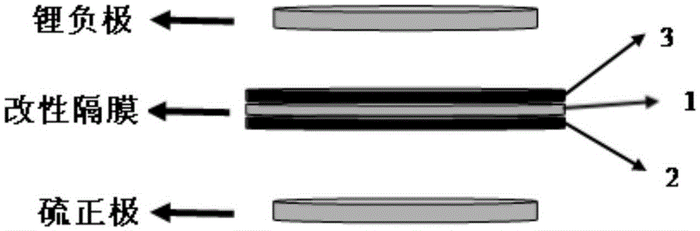
[0039] A modified diaphragm of the present invention includes a Celgard2325 diaphragm matrix (polypropylene / polyethylene / polypropylene three-layer diaphragm) and an electronic conductive coating (graphene and carbon nanotube mixed coating) on ​​both surfaces of the Celgard2325 diaphragm, and Inorganic hard coating (carbon nitride coating); the mass content of graphene in the electronic conductive coating is 50%; the thickness of the electronic conductive coating is 50 μm; the thickness of the inorganic hard coating is 50 μm.

[0040] The preparation method of the modified diaphragm of this embodiment includes the following steps:

[0041] (1) Take a Celgard2325 diaphragm, clean it with ethanol, and dry it for later use;

[0042] (2) Disperse 0.9mg carbon nitride powder and 0.1mg polyvinylidene fluoride (PVDF) in N-methylpyrrolidone (NMP) to prepare a uniform inorganic hard material slurry;

[0043] Disperse 0.5mg graphene, 0.4mg carbon nanotubes and 0.1mg polyvinylidene fluoride (PVDF...

Embodiment 2

[0050] A modified diaphragm of the present invention, comprising a polyethylene diaphragm and an electronic conductive coating (graphene and carbon nanofiber mixed coating) and an inorganic hard coating (boron carbide coating) on ​​both surfaces of the polyethylene diaphragm; The mass content of graphene in the electronic conductive coating is 40%; the thickness of the electronic conductive coating is 10 μm; the thickness of the inorganic hard coating is 10 μm.

[0051] The preparation method of the modified diaphragm of this embodiment includes the following steps:

[0052] (1) Take a polyethylene diaphragm, clean it with ethanol, and dry it for later use;

[0053] (2) Disperse 0.9 mg of boron carbide powder and 0.1 mg of polyvinylidene fluoride (PVDF) in N-methylpyrrolidone (NMP) to prepare a uniform inorganic hard material slurry;

[0054] Disperse 0.4mg graphene, 0.5mg carbon nanofibers and 0.1mg polyvinylidene fluoride (PVDF) in N-methylpyrrolidone (NMP) to prepare a uniform elec...

Embodiment 3

[0058] A modified diaphragm of the present invention includes a polypropylene diaphragm substrate and an electronic conductive coating (graphene and porous carbon mixed coating) and an inorganic hard coating (silicon nitride coating) on ​​both surfaces of the polypropylene diaphragm. The mass content of graphene in the electronic conductive coating is 20%; the thickness of the electronic conductive coating is 50 μm; the thickness of the inorganic hard coating is 50 μm.

[0059] The preparation method of the modified diaphragm of this embodiment includes the following steps:

[0060] (1) Take a polypropylene diaphragm, clean it with ethanol, and dry it for later use;

[0061] (2) Disperse 0.8 mg of silicon nitride powder and 0.2 mg of polytetrafluoroethylene (PTFE) in water to prepare a uniform inorganic hard material slurry;

[0062] Disperse 0.2mg graphene, 0.6mg porous carbon and 0.2mg polyvinylidene fluoride (PVDF) in N-methylpyrrolidone (NMP) to prepare a uniform electronic conduc...


PUM

PropertyMeasurementUnit
thicknessaaaaaaaaaa
electrical conductivityaaaaaaaaaa
thicknessaaaaaaaaaa

Abstract

The invention discloses a modified diaphragm. The modified diaphragm comprises a diaphragm substrate, and an electronic conductive coating layer and an inorganic hard coating layer positioned on the two surfaces of the diaphragm substrate respectively, wherein the electronic conductive coating layer is a mixed coating layer with graphene and a porous carbon material; and the inorganic hard coating layer is a nitrogen-carbon material coating layer, a nitrogen-silicon material coating layer, a carbon-boron material coating layer or a silicon-carbon material coating layer. The preparation method comprises the steps of uniformly coating the two surfaces of the diaphragm substrate with the electronic conductive coating layer and the inorganic hard coating layer respectively, and drying the two surfaces respectively obtain the modified diaphragm. The modified diaphragm has high diffusion and absorption capacity for an organic electrolyte, high ionic conductivity, and an obvious adsorption and blocking effect on poly-sulfur-lithium; in addition, the modified diaphragm can further restrain a shuttle effect, prevent battery short-circuit, effectively restrain the growth of negative electrode metal lithium dendrites in a cyclic process, prevent from punching the diaphragm, and protect the lithium negative electrode, so that the problem that the diaphragm is punched after dendrites formation is solved, and the safety performance of the battery is improved.

Description

Technical field [0001] The invention relates to the technical field of lithium-sulfur batteries, in particular to a modified diaphragm with double-sided modification, a preparation method thereof, and a lithium-sulfur battery. Background technique [0002] With the continuous advancement of science and technology and the rapid development of electronic products, people urgently need a battery system with high energy density and environmental friendliness, so lithium-sulfur batteries have gradually entered the field of vision of researchers. [0003] Comparing with traditional lithium ion battery cathode material LiCoO 2 , LiMn 2 O 4 , LiPFeO 4 In comparison, the sulfur cathode material for lithium-sulfur batteries has a higher theoretical specific capacity (1675mAh / g) and a higher energy density (2600Wh / kg). It is currently known as the second highest energy density other than lithium-air batteries. Secondary battery system. In addition, the positive electrode raw material is rich...

Claims


Application Information

Patent Timeline
Patent Type & Authority Applications(China)
IPC IPC(8): H01M2/14H01M2/16H01M10/052H01M50/403H01M50/431H01M50/44H01M50/446H01M50/449
CPCH01M10/052H01M50/409H01M50/403Y02E60/10
Inventor 郭华军王辉李新海王志兴彭文杰胡启阳
Owner CENT SOUTH UNIV
Why Eureka
Try Eureka