
Microscope hot stage and sample pool system used for electrochemistry in-situ Raman spectrum measurement

An in-situ Raman and spectral measurement technology, which is applied in the field of electrochemical and optical analysis, can solve the problems of not considering the dynamic adding method of samples, not considering the cooling protection of the lens, and the corrosion of the Raman microscope lens, so as to achieve good heat preservation performance and cooling Good effect, strong corrosive effect

Active Publication Date: 2016-07-06
NORTHEASTERN UNIV
View PDF8 Cites 8 Cited by
  • Summary
  • Abstract
  • Description
  • Claims
  • Application Information

AI Technical Summary

Problems solved by technology

[0007] The above test devices generally have the following problems: 1. The dynamic addition method of the sample is not considered when designing the sample cell. It is often necessary to add the sample to the sample cell before the test and then seal the sample cell. Due to the solid sample Melting and volatilization of the sample under high temperature conditions make the height of the liquid level lower than that of the solid sample before melting, which is unfavorable for the Raman microscope lens with limited focal length; 2. The heating body of the test device is often made of metal Resistance wire, and when using resistance wire to heat, in order to achieve a higher operating temperature, a longer resistance wire is often required, but due to limited space, this will bring a lot of inconvenience; 3. The microscope lens equipped with the test device is far from the high temperature area Due to the limited focal length of the Raman microscope lens during measurement, the lens is very close to the liquid surface of the sample, and the large amount of thermal radiation generated in this way will cause serious corrosion to the Raman microscope lens, which was not considered by previous researchers. The link of cooling and protecting the lens
This patent has made great improvements and innovations to the above-mentioned several test devices, and uses a quartz cover to seal the crucible sample cell, but the sample cell still has great restrictions on the use of protective gas, and the patent uses a metal resistance wire Heating the analyte

Method used


Image

  • Microscope hot stage and sample pool system used for electrochemistry in-situ Raman spectrum measurement
  • Microscope hot stage and sample pool system used for electrochemistry in-situ Raman spectrum measurement
  • Microscope hot stage and sample pool system used for electrochemistry in-situ Raman spectrum measurement

Examples


Embodiment 1

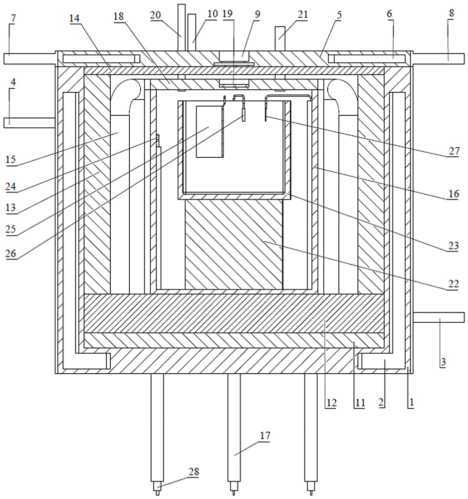
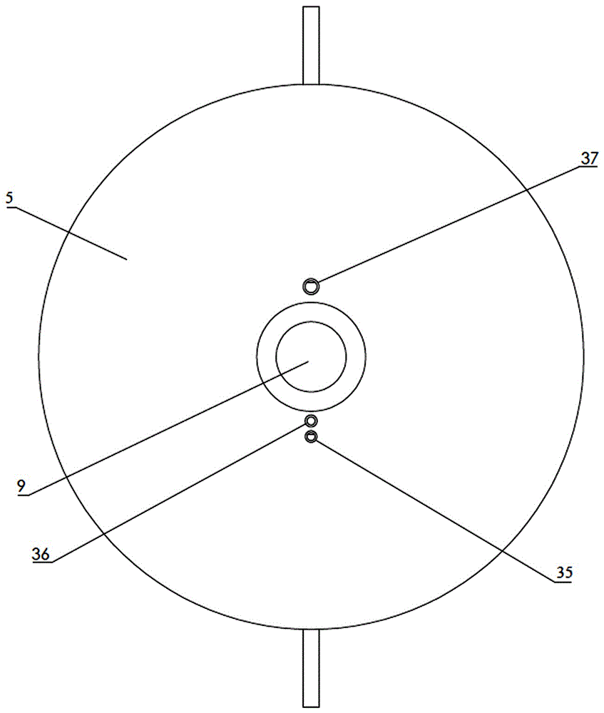
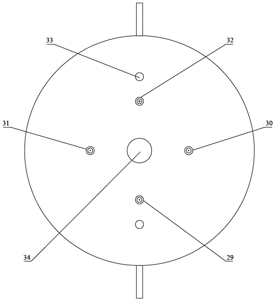
[0044] A microscopic hot stage and sample cell system for electrochemical in-situ Raman spectroscopy, such as Figure 1~3 As shown, it includes a hot stage main body 1, a hot stage cover 5, a sealed cabin, a silicon carbide rod 15, a sample pool 23 and a base 40; , the sealed cabin and the silicon carbide rod 15 are arranged on the top of the thermal insulation layer 12, and the silicon carbide rod 15 is arranged around the sealed cabin, and an annular thermal insulation layer 13 is arranged between the silicon carbide rod 15 and the inner wall of the hot stage main body 1; the sample pool 23 Placed in a sealed cabin; the outside of the bottom of the main body of the heating stage 1 is provided with a base installation hole 34 for inserting the upper pillar 41 of the base, a silicon carbide rod wire through hole 33, a thermocouple wire through hole 32, a counter electrode wire through hole 31, and a reference Electrode wire through hole 29 and working electrode wire through ho...

Embodiment 2

[0071] The microthermal stage and sample cell system for electrochemical in-situ Raman spectroscopy measurement in this embodiment are the same as those in Embodiment 1, the difference is that the system in this embodiment directly uses the sample cell as the counter electrode, and the material of the crucible used in the sample cell is graphite . Figure 10 A schematic structural diagram of the micro-heating stage and sample cell system for electrochemical in-situ Raman spectroscopy measurement of this embodiment is provided; Figure 11 A schematic diagram of the structure of the airtight cabin is provided; Figure 12 A schematic diagram of the sample cell structure is provided.

[0072] The temperature controller model used in conjunction with the microthermal table and sample cell system of the present embodiment is CKW-3100; the Raman spectrometer is a HR800 microscopic laser Raman spectrometer; the laser is an IK3301R-GHe-Cd325nm ultraviolet laser; the microscope ( lens...


PUM


Abstract

A microscope hot stage and sample pool system used for electrochemistry in-situ Raman spectrum measurement comprises a hot stage body, a hot stage cover, a sealed cabin, silicon carbide rods, a sample pool and a base. An insulating layer is arranged on the inner side of the bottom of the hot stage body. A heat preservation layer is arranged on the insulating layer. The sealed cabin and the silicon carbide rods are arranged on the upper portion of the heat preservation layer. The silicon carbide rods surround the sealed cabin. A heat preservation layer is arranged between the silicon carbide rods and the inner wall of the hot stage body. The sample pool is arranged in the sealed cabin. A base installation hole for a base upper supporting column to be inserted therein, silicon carbide rod wire through holes, a thermocouple wire through hole and an electrode wire through hole are formed in the outer side of the bottom of the hot stage body. By means of the microscope hot stage and sample pool system, protection gas can be introduced, the sealed cabin allowing samples to be dynamically added is used in cooperation with the sample pool, the silicon carbide rods convenient to install and high in heating amount are used as heating bodies, a cooling pore way with the L-shaped section is designed on the hot stage cover, cooling gas can be introduced at any time to cool a microscope lens, and advantages are provided for high-temperature fused salt Raman tests due to the design.

Description

technical field [0001] The invention belongs to the technical field of electrochemical and optical analysis, and in particular relates to a micro-heating stage and a sample cell system for electrochemical in-situ Raman spectrum measurement. Background technique [0002] Spectroelectrochemistry is a research method that combines electrochemical testing techniques with various spectroscopic techniques. According to the test method, spectroelectrochemistry can be divided into in situ type (insitu) and ex situ type (exsitu). Spectroelectrochemical technology not only has the characteristics of high energy resolution of spectroscopic technology, but also has the characteristics of high sensitivity of electrochemical testing technology. Dynamic spectroscopy (time-resolved spectroscopy) enables people to dynamically obtain optical and electrical signals in experiments, which enables the identification and capture of unstable intermediates at the molecular level, monitoring the ins...

Claims


Application Information

Patent Timeline
IPC IPC(8): G01N21/65G01N27/28
CPCG01N21/65G01N27/28G01N2021/651
Inventor 胡宪伟陈鹏黄椿森石忠宁高炳亮于江玉王兆文
Owner NORTHEASTERN UNIV
Learn More