
An in-situ force spectroscopy method based on an optical atomic magnetometer

An atomic magnetometer and optical technology, applied in chemical instruments and methods, the size/direction of magnetic field, force/torque/power measuring instrument, etc., can solve the problems of time-consuming and laborious, low measurement efficiency, and experimental error of sample increase, and achieve Reduce experimental errors, improve work efficiency, and avoid repeated transfer effects

Active Publication Date: 2019-05-14
INST OF CHEM CHINESE ACAD OF SCI +1
View PDF8 Cites 0 Cited by
  • Summary
  • Abstract
  • Description
  • Claims
  • Application Information

AI Technical Summary

Problems solved by technology

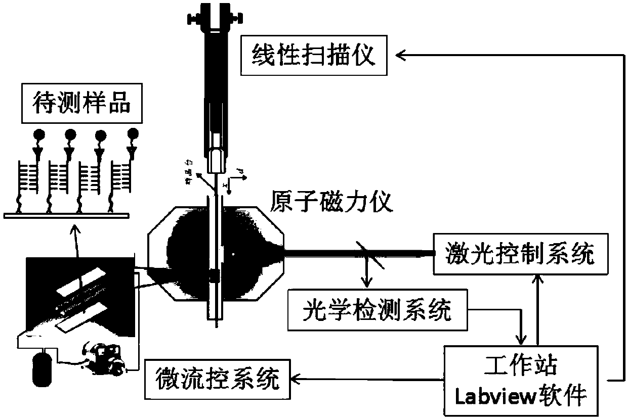
[0003] The object of the present invention is to provide an in-situ force spectroscopy method based on an optical atomic magnetometer. The atomic force spectroscopy method of the present invention solves the problem that the ultra-low field force spectroscopy method of the prior art cannot be integrated with the magnetometer, which is time-consuming, laborious, and low in measurement efficiency. , and the repeated transfer of the sample is likely to increase the experimental error, it is a new type of ultra-low field in situ force spectroscopy technique

Method used


Image

  • An in-situ force spectroscopy method based on an optical atomic magnetometer
  • An in-situ force spectroscopy method based on an optical atomic magnetometer
  • An in-situ force spectroscopy method based on an optical atomic magnetometer

Examples


Embodiment 1

[0050] Embodiment 1, the influence of installing a linear scanning device on an ultra-low field atomic magnetometer

[0051] A linear scanning device is installed in the sample channel of the optical atomic magnetometer, and its components include an X-Y-Z three-dimensional displacement motor, a sample rod, and a rotating fixed platform. Among them, the sample rod adopts a 2mm diameter quartz rod, which can be stably fixed on the axis of the inlet and outlet of the scanning channel. By optimizing the scanning speed of the electric motor and adjusting the moving direction of the sample rod, the influence of the linear scanning device on the ultra-low field atomic magnetometer is minimized.

[0052] Such as figure 2 As shown, after installing the linear scanning device, a square wave magnetic field of 1000pT is used to test the sensitivity of the ultra-low field atomic magnetometer. Using Labview software to adjust the parameters of the magnetometer, the background noise of t...

Embodiment 2

[0053] Example 2. Detecting the magnetic probe modified by the microfluidic chip on the linear scanning platform in the atomic magnetometer

[0054] Local aldylation of the central region on amino-modified glass substrates. 0.6ml 8.4mg / mlNaHCO 3 Aqueous solution, 150mg mPEG-SVA, 4mg Ald-PEG-SVA are mixed evenly, then take 1-2ul of the supernatant and add it dropwise to the center of the glass substrate, cover with a 4mm small glass slide, react at room temperature for 3 hours, and then wash with a large amount of water. Partially alhylated substrates are obtained. Add 0.6ml 8.4mg / ml NaHCO 3 Aqueous solution and 150mg mPEG-SVA were mixed evenly, and 20ul of the supernatant was added dropwise to the entire partial aldehylation substrate, covered with another partial aldehylation substrate, reacted at room temperature for 3 hours, and then washed with a large amount of water and dried.

[0055] Then, on the above-mentioned modified glass substrate, fix the polydimethylsiloxane...

Embodiment 3

[0058] Embodiment 3, Utilize the in situ force spectrum method of the present invention to measure the force-magnetic field intensity curve of double-stranded DNA (15bp)

[0059] In Example 2, a 15bp double-stranded DNA molecule is used to simultaneously control the microfluidic device and the magnetometer detection system by using Labview software, so that in-situ application of perturbation force and in-situ detection of magnetic signals can be realized. Control the flow rate in the microfluidic chip from 0 to 500 rpm, and act on each flow rate point for 3 minutes. According to the variation of the magnetic field intensity measured at different flow rates, the force-magnetic field intensity variation curve is obtained, and then the information on the force required for the molecular pair to dissociate is obtained. Such as Figure 4 As shown, a 15 bp double-stranded DNA molecule dissociates under the action of a flow rate of 180 rpm. Using the microfluidic drag force formul...


PUM

PropertyMeasurementUnit
sizeaaaaaaaaaa

Abstract

The invention discloses an in-situ force spectrum method based on an optical atomic magnetometer. The in-situ force spectrum method comprises the following steps: fixing a molecular pair labeled by a magnetic probe into a microfluidic channel of a microfluidic chip, connecting to a substrate of the microfluidic chip, and magnetizing the magnetic probe by magnet; mounting the processed microfluidic chip on a sample stage, starting a linear scanning device to scan to obtain the magnetic field strength of the molecular pair labeled by the magnetic probe; starting the optical atomic magnetometer, controlling fluid velocity in the microfluidic chip and a magnetometer detection system of the optical atomic magnetometer to obtain variation of the magnetic field strength at different fluid velocities; obtaining a variation curve of force and the variation of the magnetic field strength according to fluid mechanics, thereby detecting non-covalent interaction force between molecules of the molecular pair. The in-situ force spectrum method provided by the invention completely avoids repeatedly transferring samples in the force applying process and the measurement process, reduces the corresponding experimental error and improves the working efficiency of force spectrum measurement.

Description

technical field [0001] The invention relates to an in-situ force spectrum method based on an optical atomic magnetometer, and belongs to the technical field of biological force spectrum. Background technique [0002] Interactions between proteins, DNA and other biomacromolecules exist everywhere in organisms, and such interactions are essential to maintain the survival and normal activities of all cells. The study of the molecular mechanism of protein-DNA interaction plays an extremely important guiding role in understanding the mechanism of DNA transcription regulation and gene expression, and revealing various life activity phenomena. With the advancement of nanotechnology, people have developed a variety of single-molecule force spectroscopy methods to directly detect the interaction between biomacromolecules. Among them, ultra-low field force spectroscopy is a new technology developed on the basis of ultra-low field magnetic imaging morphology, using magnetic labeling t...

Claims


Application Information

Patent Timeline
Patent Type & Authority Patents(China)
IPC IPC(8): G01N27/72G01R33/032G01L5/00B01L3/00
CPCB01L3/5027B01L2300/0887G01L5/00G01N27/72G01R33/032
Inventor 姚立于婵婵
Owner INST OF CHEM CHINESE ACAD OF SCI
Learn More