In-situ circulating hydrate promoter capable of continuously separating carbon dioxide, apparatus and method thereof
A technology of hydrate accelerator and carbon dioxide, which is applied in separation methods, chemical instruments and methods, and separation of dispersed particles, and can solve problems such as high operating costs, complex processes, and inability to achieve continuous absorption.
- Summary
- Abstract
- Description
- Claims
- Application Information
AI Technical Summary
Problems solved by technology
Method used
Image

Examples
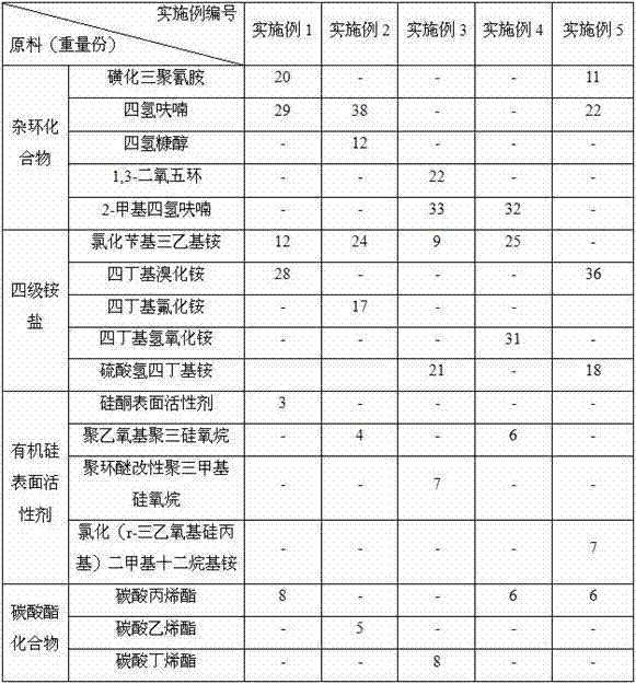
Embodiment 1~5
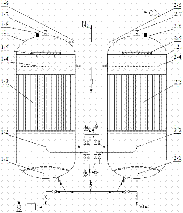
[0050] like figure 1 As shown, a device for continuously separating carbon dioxide, the device is a double-tower circulation capture tower 1, 2 with the same structure; Gas and liquid discharge device 1-1, 2-1, cold / heat exchange device 1-2, 2-2, wire mesh large space capture-release bed 1-3, 2-3, atomization spray device 1 -4, 2-4, liquid-gas separation device 1-5, 2-5, the top of the double-tower circulation trapping tower 1, 2 is also equipped with rich N 2 Discharge line 1-6, 2-6, CO 2 Discharge pipelines 1-7, 2-7 and temperature and pressure sensing devices 1-8, 2-8; the N-rich 2 There are CO on the discharge pipeline 1-6 and 2-6 2 online monitor, the CO 2 N 2 , O 2 On-line monitor; the gas distribution and liquid discharge devices 1-1 and 2-1 are connected to the atomizing spray devices 1-4 and 2-4 at the same time, and can be installed in the double-tower circulation capture towers 1 and 2 Switch between them at will; the wire mesh large space capture-release bed...
Embodiment 1
[0052] The main component (v / v) of the captured flue gas in this example is N 2 : 76%, CO 2 : 18%, O 2 : 5.6%.
[0053] Firstly, the in-situ circulating hydrate accelerator for continuous separation of carbon dioxide in Example 1 is made into an aqueous solution with a mass concentration of 5.8%; when capturing CO 2 When the flow pressure of the flue gas is 0.31MPa and the temperature is 4.5°C, the in-situ circulating hydrate accelerator solution of the flue gas and the atomized continuous separation of carbon dioxide flows in the opposite direction, and is captured in the large space of the wire mesh- In the release bed 1-3 or 2-3, CO in the flue gas is realized 2 continuous capture; when releasing CO 2 , reduce the pressure to 0.1013MPa, and raise the temperature to 95°C to realize the in-situ disintegration and release of the solid crystalline hydrate solidified in the large-space capture-release bed of the wire mesh to remove CO 2 ;
[0054] like figure 1 As shown, ...
Embodiment 2
[0060] The main component (v / v) of the captured flue gas in this example is N 2 : 72.9%, CO 2 : 22.2%, O 2 : 4.7%.
[0061] Firstly, the in-situ circulating hydrate accelerator for continuous separation of carbon dioxide in Example 2 is made into an aqueous solution with a mass concentration of 9.5%; when capturing CO 2 When the flow pressure of the flue gas is 0.27MPa and the temperature is 8°C, the in-situ circulating hydrate accelerator solution of the flue gas and the continuously separated carbon dioxide after atomization flows in the opposite direction, and is captured in the large space of the wire mesh- In the release bed 1-3 or 2-3, CO in the flue gas is realized 2 continuous capture; when releasing CO 2 , reduce the pressure to 0.08MPa, and raise the temperature to 75°C to realize the in-situ disintegration and release of the solid crystalline hydrate solidified in the large-space capture-release bed of the wire mesh to remove CO 2 ;
[0062] The double-tower c...
PUM
 Abstract
Description
Claims
Application Information
PatSnap Eureka turns technology decisions into work you can execute. Powered by our Innovation Knowledge Graph, it runs expert workflows across engineering, life sciences, materials and intellectual property. Get your review-ready output in minutes.


