Nitrogen-cycled methane washing system and method for separating CO and H2 in deep cooling manner

A technology of cryogenic separation and nitrogen circulation, which is applied in the field of nitrogen circulation methane washing system for cryogenic separation of CO and H2, can solve the problems of low efficiency of CO compressor and expander, large amount of venting in the start-up stage, and high pressure of circulating nitrogen, To achieve the effect of reducing the amount of venting, reducing the power consumption of rectification and improving the recovery rate

Active Publication Date: 2017-11-21
四川蜀道装备科技股份有限公司
View PDF7 Cites 12 Cited by
  • Summary
  • Abstract
  • Description
  • Claims
  • Application Information

AI Technical Summary

Problems solved by technology

[0004] Chinese Invention Patent Grant No. CN 101680713 B "Method for Separating Mixtures Containing Carbon Monoxide, Methane, Hydrogen and Optional Nitrogen by Low-Temperature Distillation" and US Patent US 6578377 B1'Recovery of hydrogen and carbon monoxide from mixtures including methane and hydrocarbons heavier thanmethane' Both use pure CO compression and refrigeration cycles. In view of the low efficiency and high technical requirements of the CO compressor and expander, the energy consumption and investment of this process are relatively large. At the same time, the purity of the circulating refrigerant CO causes the device to start, The purification time is long, and the venting volume in the start-up stage is large
[0005] Chinese Invention Patent Application No. CN 201510014944.9 "A Method and Device for Efficiently Separating Synthesis Gas to Produce Hydrogen and Carbon Monoxide". The device uses liquid nitrogen as a cold source. This process requires high pressure and large flow rate of circulating nitrogen, which has the disadvantage of high energy consumption, and the pressure of CO products is low.

Method used


Image

  • Nitrogen-cycled methane washing system and method for separating CO and H2 in deep cooling manner
  • Nitrogen-cycled methane washing system and method for separating CO and H2 in deep cooling manner
  • Nitrogen-cycled methane washing system and method for separating CO and H2 in deep cooling manner

Examples


Embodiment 1

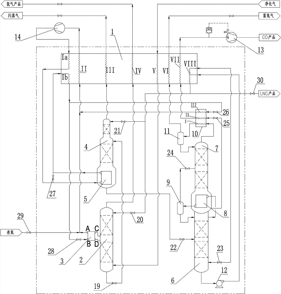
[0035] Embodiment one: if figure 1 As shown, a cryogenic separation of CO, H 2 The nitrogen cycle methane scrubbing system includes a main heat exchanger 1, a methane scrubber 2, a side condenser 3, a hydrogen stripper 4, a hydrogen stripper bottom evaporator 5, a demethanizer 6, and a nitrogen removal tower 7 , condensing evaporator 8, demethanizer overhead separator 9, denitrification tower overhead condenser 10, denitrification tower overhead separator 11, methane liquid pump 12, CO product compressor 13 and circulating nitrogen compressor 14, The main heat exchanger 1 is provided with a flow channel Ia, a flow channel Ib, a flow channel II, a flow channel III, a flow channel IV, a flow channel V, a flow channel VI, a flow channel VII and a flow channel VIII, and the denitrification tower The top condenser 10 is provided with flow passage I, flow passage II and flow passage III, the condensation evaporator 8 is arranged between the demethanizer 6 and the denitrification to...

Embodiment 2

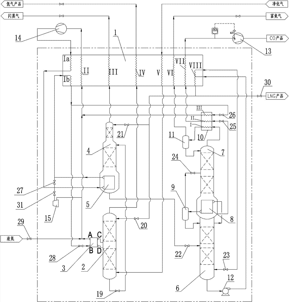
[0048] Embodiment two: if figure 2 As shown, the difference between the present embodiment and the first embodiment is that a flow of material is added at the outlet of the main heat exchanger 1 flow channel Ia, and is sent to the inlet of the turboexpander 15 after the valve M31, and the outlet of the turboexpander 15 The outlet is connected with the low-pressure nitrogen main pipe, and when the system is started or the cooling capacity is insufficient, the turbo expander 15 is used to produce cooling capacity.

Embodiment 3

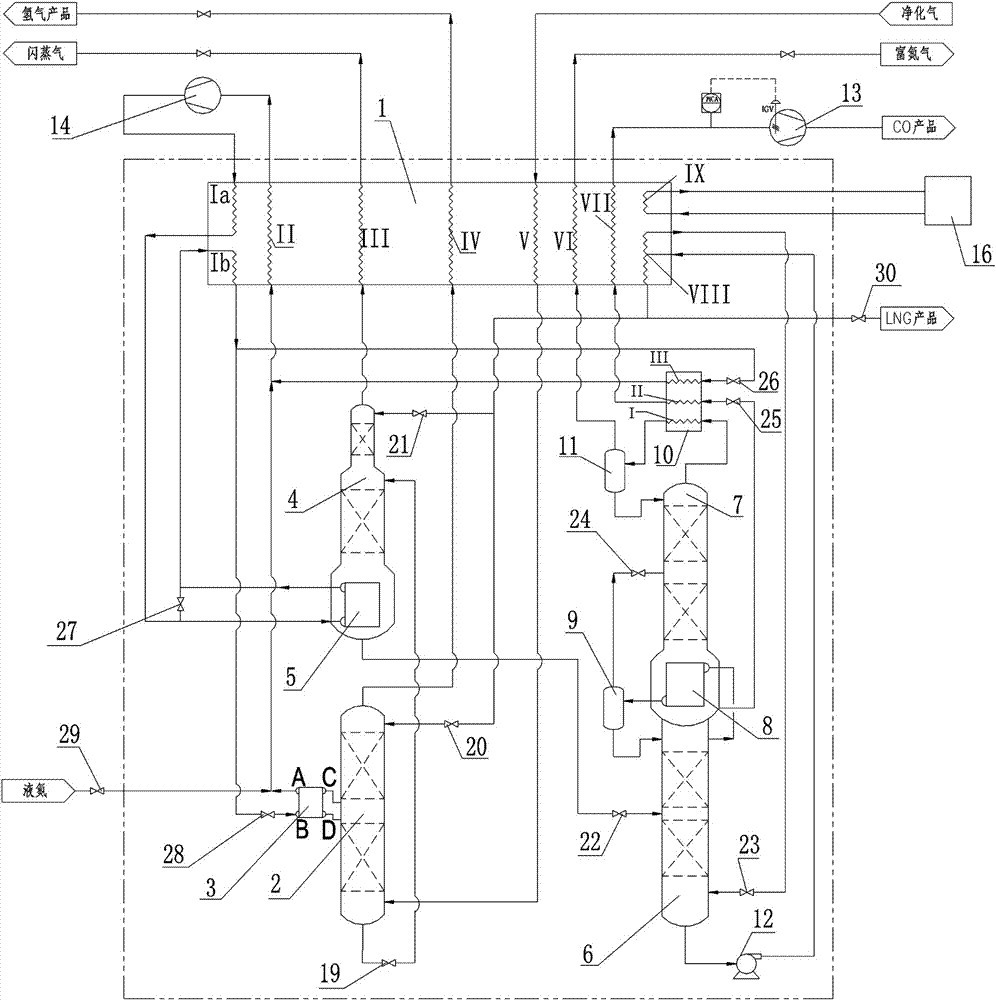
[0049]Embodiment three: as image 3 As shown, the difference between the present embodiment and the first embodiment is that the main heat exchanger 1 has a flow channel IX and is connected with the low-temperature pre-cooling unit 16 to provide cooling capacity for the system at a temperature of -40~40°C.


PUM


Abstract

The invention discloses a nitrogen-cycled methane washing system for separating CO and H2 in a deep cooling manner. The nitrogen-cycled methane washing system comprises a main heat exchanger, a methane washing tower, a hydrogen gas extraction tower, a demethanation tower, a denitrification tower, a condensation evaporator, a methane liquid pump, a cycled-nitrogen compressor and a CO product compressor. The invention further discloses a nitrogen-cycled methane washing method for separating the CO and H2 in the deep cooling manner. The method comprises the steps of heat exchange, methane washing, dehydrogenation, demethanation, denitrification, nitrogen gas compression and refrigeration cycle, CO product compression and the like. The nitrogen-cycled methane washing system and method have the beneficial effects that the methane washing method is adopted to produce the H2, the energy consumption and investment for producing the H2 are greatly lowered, and the recycling rate of the CO and the H2 can also be increased; the nitrogen cycle compression and refrigeration process is adopted, and high efficiency and low investment of a nitrogen compressor are fully played; the condensation evaporator is arranged, the demethanation tower and the denitrification tower are integrally connected ingeniously, and rectification energy consumption is greatly lowered; the start and purification time of a device can also be shortened, and the venting amount in the start stage is reduced; and good economic benefits and environmentally-friendly benefits are achieved.

Description

technical field [0001] The invention relates to the field of cryogenic gas separation, in particular to a cryogenic separation of CO and H 2 A nitrogen cycle methane scrubbing system and method. Background technique [0002] CO is an important raw material gas for oxo synthesis, and almost all organic chemicals can be prepared from CO. At present, the synthesis gas for producing CO mainly comes from coal pressurized gasification, natural gas / naphtha steam reforming or coke oven gas. In addition to CO, H 2 In addition, it also contains a small amount of methane, nitrogen and argon. In view of the high purity requirements of raw material CO (≥98.5%) in the production of chemical products such as ethylene glycol, acetic acid and dimethyl diamide, it is necessary to convert the synthesis gas The removal of hydrogen, methane, nitrogen and argon in the process. Cryogenic separation technology has mature technology, stable operation, large processing capacity, high product purit...

Claims


Application Information

Patent Timeline
Patent Type & Authority Applications(China)
IPC IPC(8): F25J3/02
CPCF25J3/0223F25J3/0271F25J2270/90F25J2200/74F25J2270/904F25J3/0252F25J2205/04F25J2270/02F25J3/0257F25J3/0233F25J2205/30F25J2235/60F25J2210/42F25J2270/42F25J2270/12F25J2235/02F25J3/0261F25J2270/14F25J2200/06F25J2200/40F25J2215/04F25J2290/34
Inventor 曹卫华文向南
Owner 四川蜀道装备科技股份有限公司
Why Eureka
Try Eureka