Low-rank fuel low-temperature gasification device based on screw pyrolyzers and fluidized bed gasifier

A technology of low-temperature gasification and pyrolyzer, applied in the details of gasification device, gasification process, gasification of granular/powdered fuel, etc., can solve the problems of tar removal without consideration, high investment and operating costs, cold gasification efficiency Reduce the problem of reduction, achieve the effect of reducing tar content, prolonging residence time and high carbon conversion rate

Active Publication Date: 2017-11-28
哈尔滨丰瀛投资有限公司
View PDF6 Cites 2 Cited by
  • Summary
  • Abstract
  • Description
  • Claims
  • Application Information

AI Technical Summary

Problems solved by technology

[0006] However, in terms of tar removal, the existing patents only remove tar through catalytic cracking of high-temperature coke tar or high-temperature cracking of tar itself in the gasification stage. The gasification temperature is relatively high, while tar removal in the pyrolysis stage Except not considered; higher gasification temperature will inevitably lead to lower cold gasification efficiency (for coal, cold gasification efficiency), when the gasification temperature increases from 900 °C to 1600 °C, the cold gasification efficiency drops by 20 %about
In terms of coke gasification, the existing patents increase the gasification rate by increasing the temperature or pressure, which makes insufficient use of alkali metal and alkaline earth metal catalysts in low-order fuels; higher gasification temperature and pressure will also lead to higher investment and operating costs

Method used


Image

  • Low-rank fuel low-temperature gasification device based on screw pyrolyzers and fluidized bed gasifier
  • Low-rank fuel low-temperature gasification device based on screw pyrolyzers and fluidized bed gasifier
  • Low-rank fuel low-temperature gasification device based on screw pyrolyzers and fluidized bed gasifier

Examples


specific Embodiment approach 1

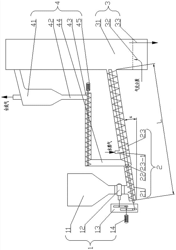
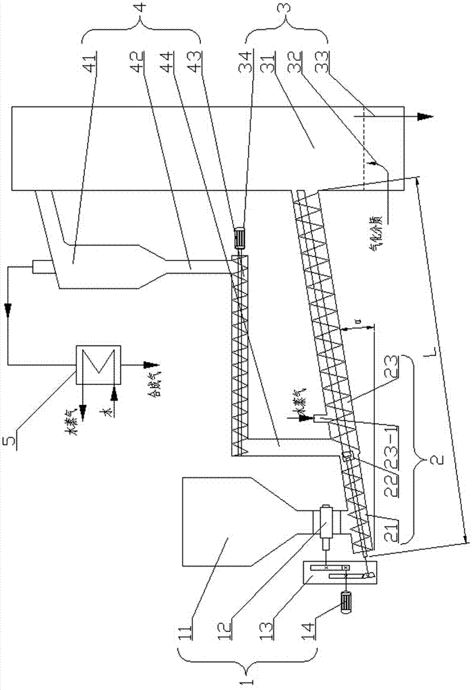
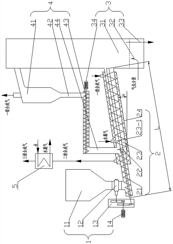
[0032] Specific implementation mode one: as figure 1 , Figure 4 As shown, this embodiment discloses a low-stage fuel low-temperature gasification device based on a spiral pyrolyzer and a fluidized bed gasifier, which consists of a storage system 1, a spiral pyrolysis system 2, a fluidized bed gasification System 3 and cyclone separation system 4;

[0033] The storage system 1 includes a silo 11, an air lock 12, a gear box 13 and a motor 14, and the spiral pyrolysis system 2 includes a primary spiral pyrolyzer 21, a coupling 22 and a secondary spiral Pyrolyzer 23, the fluidized bed gasification system 3 includes a fluidized bed gasifier 31, an air intake system 32 and a slag discharge pipe 33, and the cyclone separation system 4 includes a spiral feeder 43, a secondary A return pipe 44, at least one cyclone separator 41 and at least one primary return pipe 42;

[0034] The air shutoff device 12 is arranged at the lower part of the silo 11, the power output shaft of the moto...

specific Embodiment approach 2

[0041] Specific implementation mode two: as figure 1 As shown, this embodiment is a further description of Embodiment 1. The angle between the bottom surface of the spiral pyrolysis system 2 and the horizontal plane is α, and α=5°~45°. Ensure the fullness of the pyrolysis product in the spiral pyrolyzer, so that the volatile matter can only diffuse out through the solid product layer, so as to fully react with it.

specific Embodiment approach 3

[0042] Specific implementation mode three: as figure 1 As shown, this embodiment is a further description of specific embodiment one. Suppose the length of the spiral pyrolysis system 2 is L, and the initial position of the length of the spiral pyrolysis system 2 is located at the fuel of the first-stage spiral pyrolysis device 21. At the inlet end, the docking position of the outer cylinder of the first-stage spiral pyrolyzer 21 and the outer cylinder of the second-stage spiral pyrolyzer 23 is set in the 1 / 3L area of ​​the spiral pyrolysis system 2 in the length direction. Ensure sufficient contact and heat transfer between the heat carrier and the input low-order fuel in the secondary spiral pyrolyzer 23 .

[0043] Specific implementation mode four: as figure 1 As shown, this embodiment is a further description of the third embodiment, and the water vapor inlet 23-1 is set close to the fuel inlet.

[0044] It is used to make up for the lack of water in the gas phase (inclu...


PUM


Abstract

A low-rank fuel low-temperature gasification device based on screw pyrolyzers and a fluidized bed gasifier belongs to the field of gasification of low-rank fuels. The power output shaft of a motor 1 is connected with the power input shaft of a transmission gearbox in a transmission mode, a first-order screw pyrolyzer is mutually coupled with a gas lock device through a transmission gearbox, the screw shaft of the first-order screw pyrolyzer is connected with the screw shaft of a second-order screw pyrolyzer through a shaft coupling, and the second-order screw pyrolyzer communicates with the fluidized bed gasifier; the upper part of the second-order screw pyrolyzer is provided with a water vapor inlet; the fluidized bed gasifier communicates with a cyclone separator, the fluidized bed gasifier communicates with a gas inlet system, and a residue discharging tube communicates with the bottom of the fluidized bed gasifier; and the cyclone separator communicates with a first-stage return tube, the first-order return tube communicates with a screw return device, the screw return device communicates with a second-order return tube, and the second-order return tube communicates with the second-order screw pyrolyzer. The in-situ catalytic cracking of parts of tar by pyrolytic coke and the re-adsorbed alkali metal and alkali earth metal catalyzed low-temperature gasification of coal coke are used to realize the high-efficiency low-temperature gasification of the low-rank fuel.

Description

technical field [0001] The invention relates to a low-grade fuel low-temperature gasification device based on a spiral pyrolyzer and a fluidized bed gasifier, belonging to the field of low-grade fuel gasification. Background technique [0002] Gasification refers to the use of carbon-containing fuels (coal, coal char or biomass, etc.) as raw materials, oxygen (air, oxygen-enriched or industrial pure oxygen), water vapor, carbon dioxide, etc. A series of chemical reactions occur at a certain temperature and pressure to convert solid fuel into CO, H 2 、CH 4 Process such as combustible gas. [0003] Low-rank fuels (low-rank coal, biomass, and kitchen waste) are rich in reserves and sources, with low metamorphism, high volatile content, and high gasification activity. In addition, the alkali metals and alkaline earth metals rich in low-rank fuels (low-rank coal is rich in sodium, calcium and magnesium, biomass is rich in potassium, calcium and magnesium, and kitchen waste mai...

Claims


Application Information

Patent Timeline
Patent Type & Authority Applications(China)
IPC IPC(8): C10J3/66C10J3/56C10J3/72C10J3/84
CPCC10J3/56C10J3/66C10J3/72C10J3/84C10J2200/154C10J2300/1807
Inventor 刘辉许连飞姜雷霄曹庆喜高继慧吴少华
Owner 哈尔滨丰瀛投资有限公司
Why Eureka
Try Eureka