
Microwire array optical detector and preparation method thereof

A photodetector, micron wire technology, applied in semiconductor devices, final product manufacturing, sustainable manufacturing/processing, etc. Problems such as low fault tolerance of a single nanowire

Active Publication Date: 2017-12-08
SOUTH CHINA NORMAL UNIVERSITY
View PDF3 Cites 16 Cited by
  • Summary
  • Abstract
  • Description
  • Claims
  • Application Information

AI Technical Summary

Problems solved by technology

[0004] However, a single one-dimensional micro-nano device has its inherent defects. For example, due to its small light-receiving area, it is very susceptible to external disturbances. Once the point light source is shaken and deviates from a single nanowire, the detector cannot detect the light. signal, which leads to a low fault tolerance rate of a single nanowire, which is not conducive to practical applications; secondly, the photogenerated carrier area of ​​a single device is limited, so the photocurrent intensity is greatly limited
The above two defects lead to the low sensitivity and photoresponse of a single one-dimensional micro-nano photodetector, which hinders its further development.

Method used


Image

  • Microwire array optical detector and preparation method thereof
  • Microwire array optical detector and preparation method thereof
  • Microwire array optical detector and preparation method thereof

Examples


preparation example Construction

[0060] The present invention also provides a method for preparing a micron line array photodetector described in the above technical solution, comprising the following steps:

[0061] (1) Etching a silicon wafer with an insulating layer to obtain a patterned substrate with a plurality of parallel trench arrays;

[0062] (2) In the step (1), gallium nitride micro-wires are epitaxially grown on the inner side walls of the trenches, and a gallium nitride micro-wires are respectively grown on the two inner side walls of each trench to form an epitaxial structure on the substrate surface ;

[0063] (3) In the step (2), both ends of the gallium nitride microwires are covered with Schottky contact type metal electrodes to obtain a micrometer wire array photodetector.

[0064] The invention etches the silicon wafer with the insulating layer to obtain a patterned substrate with a plurality of parallel trench arrays. In the present invention, there is no special limitation on the sour...

Embodiment 1

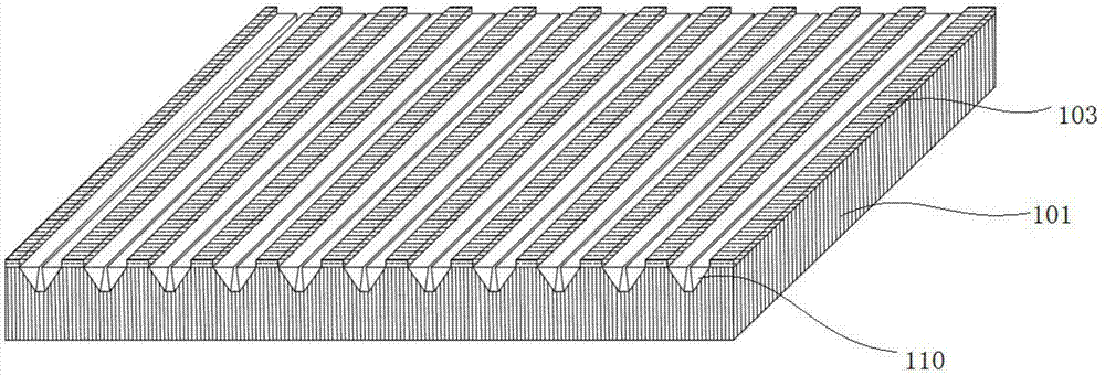
[0076] The structure of the micron line array ultraviolet photodetector prepared in this embodiment is as follows: Figure 1~5 As shown, the optical micrograph of the micron line array photodetector in the present embodiment is as follows Figure 11 Shown: the substrate material 100 is a silicon wafer with a crystal orientation of , the silicon wafer is an intrinsic material, and the resistivity is as high as 10 4 Ω·cm; the insulating layer 103 covers the silicon surface and is a layer of SiO with a thickness of 300nm 2 , the width of the insulating layer is 5 microns; the width of the trench is 2 microns; the epitaxial structure 110 is epitaxial on the sidewall of the trench 102 of the high-resistance silicon substrate, and the epitaxial structure successively includes an aluminum nitride buffer layer 111 with a thickness of 30 nm and a gallium nitride epitaxial layer 112 with a thickness of 300nm, the AlN buffer layer 111 is stacked on the trench side 102 of the intrinsic s...

Embodiment 2

[0097] According to the method of embodiment 1, micron line array photodetectors are prepared, and the specific structure is as follows Figure 6-10 Shown: the substrate material 100 is a 2-inch intrinsic silicon wafer material with a crystal orientation of , and the resistivity is as high as 10 3 Ω·cm; the insulating layer 103 covers the silicon surface and is a layer of SiO with a thickness of 150nm 2 The epitaxial structure 110 is epitaxial on the sidewall of the high-resistance silicon substrate trench 102, and its epitaxial structure includes an aluminum nitride buffer layer 111 and a gallium nitride epitaxial layer 112 in sequence, and the AlN buffer layer 111 is stacked on the intrinsic On the groove side 102 of the silicon substrate, the gallium nitride epitaxial layer 112 is stacked on the aluminum nitride buffer layer 111; since the crystal orientation of the substrate is different from that of Embodiment 1, the cross-sectional shape of the groove will change from ...


PUM


Abstract

The invention discloses a microwire array optical detector and a preparation method thereof. According to the invention, the microwire array optical detector includes a substrate, an epitaxial structure and an electrode structure. The substrate includes a silicon wafer which is provided with a plurality of trenches on the surface thereof. The trenches are distributed in parallel arrays. The silicon wafer among the trenches is provided with an insulating layer on the upper surface thereof. The epitaxial structure includes a gallium nitride microwire which epitaxially grows on the internal side wall of the trenches, the two internal side walls of each trench separately grows a gallium nitride microwire which is the same direction as the trenches, and the gallium nitride microwires inside the trenches constitute a parallel microwire array. The electrode structure includes a pair of schottky contact type metal electrodes which cover two ends of the gallium nitride microwire. According to the invention, the microwire array optical detector has higher sensitivity and response speed.

Description

technical field [0001] The invention relates to the technical field of photoelectric element preparation, in particular to a micron line array photodetector and a preparation method thereof. Background technique [0002] With the development of science and technology, detection technology is playing an increasingly important role in various fields. For example, in the military, light detection technology is used for missile early warning, optical communication, biochemical analysis, etc.; in civilian use, light detection technology is used in open flame detection, ozone monitoring, offshore oil monitoring, etc. Driven by the traction of military needs and the development of related technologies, the application of detection technology as a high-tech will be more extensive in the future and its status will be more important. With the rapid progress of research on third-generation semiconductor materials, people began to develop a new generation of semiconductor photodetector...

Claims


Application Information

Patent Timeline
Patent Type & Authority Applications(China)
IPC IPC(8): H01L31/0352H01L31/108H01L31/18
CPCH01L31/035281H01L31/108H01L31/1852H01L31/1856Y02P70/50
Inventor 李述体郭德霄赵亮亮宋伟东
Owner SOUTH CHINA NORMAL UNIVERSITY
Learn More