
A nanometer porous high-entropy alloy electrode, a preparing method thereof and applications of the electrode

A high-entropy alloy, nano-porous technology, applied in the direction of electrodes, electrode shape/type, electrolysis process, etc., to achieve the effect of rich raw material content, good conductivity, and low price

Active Publication Date: 2018-01-16
宁波杰士兄弟工具有限公司
View PDF2 Cites 43 Cited by
  • Summary
  • Abstract
  • Description
  • Claims
  • Application Information

AI Technical Summary

Problems solved by technology

[0003] However, it is related to whether the high-entropy alloy with simple structure and unique performance has the performance of high-efficiency catalytic energy storage, and there are no related reports.

Method used

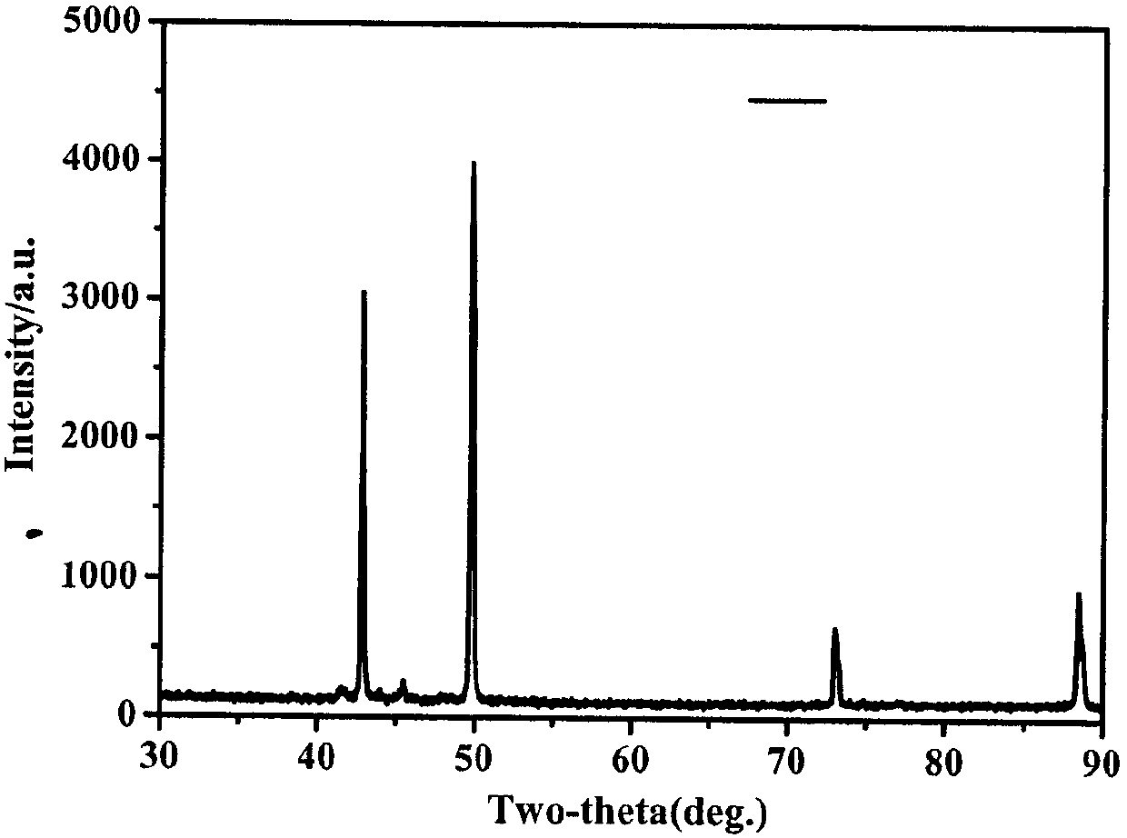
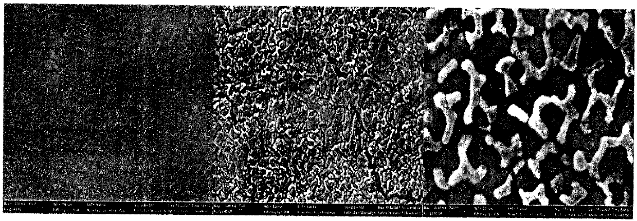
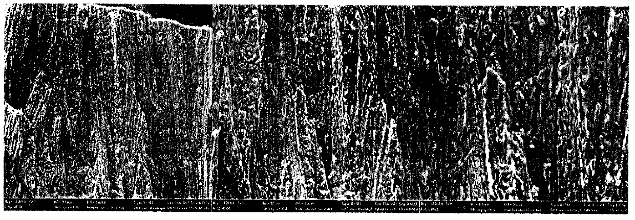

Image

  • A nanometer porous high-entropy alloy electrode, a preparing method thereof and applications of the electrode
  • A nanometer porous high-entropy alloy electrode, a preparing method thereof and applications of the electrode
  • A nanometer porous high-entropy alloy electrode, a preparing method thereof and applications of the electrode

Examples


Embodiment 1

[0027] The preparation method of the nanoporous high-entropy alloy catalytic electrode proposed in this embodiment includes the following steps:

[0028] (1) Prepare alloy: prepare nickel-iron-molybdenum-manganese-cobalt alloy, five kinds of metals Ni:Fe:Mo:Mn:Co are put into smelting furnace according to the ratio of substance amount of 15:15:8:54:8, Melted in a high vacuum melting furnace to form an alloy.

[0029] (2) The alloy strip is obtained by stripping in a strip stripping machine, the width of the alloy strip is 2 mm, and the thickness is 25 μm.

[0030] (3) Dealloying to prepare nanoporous high-entropy alloy electrodes.

[0031] Dealloying adopts electrochemical dealloying method in step screw (3), and concrete steps are as follows:

[0032] The alloy strip prepared in step (2) was prepared by electrochemical dealloying method to prepare nanoporous high-entropy alloy electrode. The dealloying step was: 1mol / L sulfuric acid bismuth was used as dealloying solution, ...

Embodiment 2

[0042] The only difference from Example 1 is that the dealloying time is changed to 1800 seconds. The catalytic performance of the obtained catalytic electrode: catalytic water electrolysis hydrogen production, at a current density of 100mA / cm 2 and 200mA / cm 2 , the overpotentials are 196mV and 278mV respectively; catalytic water electrolysis produces oxygen, and the current density is 10mA / cm 2 and 100mA / cm 2 , the overpotentials were 298mV and 442mV, respectively.

Embodiment 3

[0044] The only difference from Example 1 is that the dealloying time is changed to 3600 seconds. The catalytic performance of the obtained catalytic electrode: catalytic water electrolysis hydrogen production, at a current density of 100mA / cm 2 and 200mA / cm 2 , the overpotentials are 153mV and 252mV respectively; catalytic water electrolysis produces oxygen, and the current density is 10mA / cm 2 and 100mA / cm 2 , the overpotentials were 273mV and 423mV, respectively.


PUM

PropertyMeasurementUnit
Widthaaaaaaaaaa
Thicknessaaaaaaaaaa
Current densityaaaaaaaaaa

Abstract

The invention belongs to the technical field of catalytic and energy storage applications of high-entropy alloys, and particularly relates to a nanometer porous high-entropy alloy catalytic electrode,a preparing method thereof and applications of the electrode in bi-functional catalytic water splitting to produce hydrogen and oxygen. The electrode includes, by mole, 15-50% of Ni, 5-20% of a transition metal A, 15-50% of Mo, 5-25% of a transition metal B and 5-40% of Mn, wherein the transition metal A is Fe or Cu, and the transition metal B is one of Co, Ti or W. The alloy electrode has a porous structure, pore diameters range from 2 nm to 500 nm, and the specific surface area is 10-80 m<2> / g. The alloy electrode has advantages of 1) capability of being three-dimensional, porous, self-supporting and no need of any support or adhesive; 2) a large specific surface area and good electrical conductivity; 3) a simple material structure of the non-noble-metal porous high-entropy electrode, rich raw material sources, low prices and controllable preparation conditions; and 4) excellent catalytic performance.

Description

technical field [0001] The invention belongs to the technical field of application of high-entropy alloys in catalysis and energy storage, and in particular relates to a nanoporous high-entropy alloy catalytic electrode and its preparation method and its application in dual-functional catalytic water splitting for hydrogen and oxygen production. Background technique [0002] The conversion of non-polluting intermittent energy such as solar energy, wind energy, and water energy into controllable and transportable hydrogen energy has attracted widespread attention as one of the most promising new energy sources to solve the energy crisis and environmental pollution. However, the cell voltage of traditional water electrolysis for hydrogen production is much higher than the theoretical decomposition voltage of water (1.23V), which consumes a lot of energy and is inefficient, and effective catalytic electrodes such as platinum-based noble metals, iridium, and ruthenium-based oxide...

Claims


Application Information

Patent Timeline
IPC IPC(8): C25B1/04C25B11/03C25B11/06C22C30/00C22C30/02C22C19/03C22C27/04C22C3/00
CPCY02E60/36
Inventor 康建立张国良黄钦
Owner 宁波杰士兄弟工具有限公司
Learn More