
High-performance and long-service-life space equipment precise conductive slip ring and preparing method thereof

A technology of conductive slip rings and conductive rings, which is applied in the direction of circuits, current collectors, electrical components, etc., can solve the problems of high relative density, high material cost, and complicated manufacturing process, so as to inhibit oxidation, reduce contact area, and improve conversion efficiency Effect

Active Publication Date: 2018-03-13
ACADEMY OF ARMORED FORCES ENG PLA
View PDF4 Cites 2 Cited by
  • Summary
  • Abstract
  • Description
  • Claims
  • Application Information

AI Technical Summary

Problems solved by technology

[0005] The conductive slip rings currently used mainly have the following disadvantages: 1. After working for a period of time, since the conductive slip rings are made of precious metals such as gold, silver, and copper, the texture is relatively soft, and the relative movement of the contact surface with the brush will cause the ring surface of the conductive slip ring to The scratches and surface materials fall off, resulting in abrasive wear, and deep scratches will appear on the outer circle of the conductive slip ring
Due to the particularity of the working environment of the spacecraft, once the conductive slip ring fails or is damaged, it cannot be repaired or replaced. In severe cases, the normal operation of the entire spacecraft may be interrupted. Therefore, the conductive slip ring must have a long Long working life and high reliability of long-term stable work
2. The existing conductive slip rings are processed with precious metal materials, and the relative density of the materials is relatively high. While having excellent electrical conductivity, the quality of the conductive slip rings is increased, which increases the burden on the energy consumption of the spacecraft and increases the size of the spacecraft. energy loss
3. At present, the raw materials for manufacturing conductive slip rings are precious metals such as gold, silver and copper, and most of them are overall homogeneous composite materials or single precious metal materials. The material cost is high and the manufacturing process is complicated. The space conductive slip rings have stricter precision requirements. The production of precision conductive slip rings is expensive
[0006] In the prior art, in order to improve the performance of the conductive slip ring, the design and modification are mainly carried out on its structure. At present, no conductive slip ring structure with spray coating has been seen at home and abroad.

Method used


Image

  • High-performance and long-service-life space equipment precise conductive slip ring and preparing method thereof
  • High-performance and long-service-life space equipment precise conductive slip ring and preparing method thereof

Examples


Embodiment 1

[0058] (1) Preparation of Cu-TiO by ultrasonic dispersion and spray drying 2 Composite powder

[0059] 1) In terms of mass percentage, take 18% of Cu powder with an average particle size of 15 μm and 82% of nano-TiO with an average particle size of 60 nm 2 The powder is doped and mixed to obtain a mixed powder;

[0060] 2) In terms of mass percentage, take 35% mixed powder, 63% deionized water and 2% polyvinyl alcohol and mix them and stir to obtain a mixed slurry;

[0061] 3) Place the mixed slurry obtained in step 2) in an ultrasonic reactor, and continuously ultrasonically disperse at a frequency of 50 Hz and a temperature of 50°C for 3 hours. During the ultrasonic dispersion process, add 0.8% of the total weight of the slurry to the slurry % dispersant SND 6800;

[0062] 4) Use the LGZ-25 centrifugal spray dryer to spray and granulate the slurry obtained in step 3) by ultrasonic dispersion. The selected spray drying parameters are shown in Table 1. After spray granulati...

Embodiment 2

[0071] (1) Preparation of Cu-TiO by ultrasonic dispersion and spray drying 2 Composite powder

[0072] 1) In terms of mass percentage, take 20% of Cu powder with an average particle size of 15 μm and 80% of nano-TiO with an average particle size of 60 nm 2 The powder is doped and mixed to obtain a mixed powder;

[0073] 2) In terms of mass percentage, take 25% mixed powder, 73.5% deionized water and 1.5% polyvinyl alcohol and mix them and stir to obtain a mixed slurry;

[0074] 3) Place the mixed slurry obtained in step 2) in an ultrasonic reactor, and continuously ultrasonically disperse it at a frequency of 55 Hz and a temperature of 52°C for 4 hours. During the ultrasonic dispersion process, add 0.5% of the total weight of the slurry to the slurry % dispersant SND 6800;

[0075] 4) Use the LGZ-25 centrifugal spray dryer to spray and granulate the slurry obtained in step 3) by ultrasonic dispersion. The selected spray drying parameters are shown in Table 1. After spray gr...


PUM


Abstract

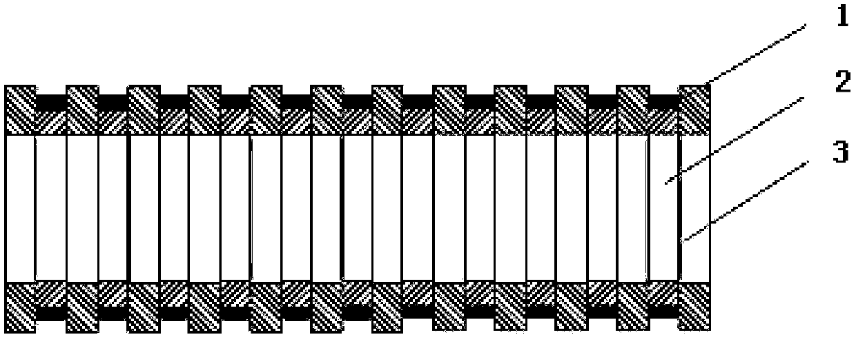
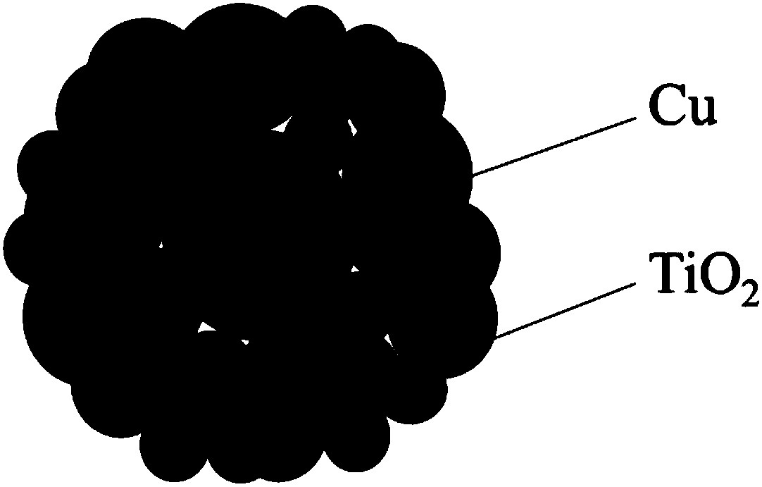
The invention relates to a high-performance and long-service-life space equipment precise conductive slip ring and a preparing method thereof. The conductive slip ring is composed of a single metal base body and a conductive abrasion resisting, corrosion preventing and self-lubricating integrated coating. The surface coating is formed in the manner that Cu-TiO2 composite powder of a core-shell structure is directly subjected to plasma spraying to a slip ring base body. The coating comprises components including, by mass percent, 62%-75% of Ti4O7, 12%-20% of Cu, 10%-15% of TixO2x-1 and 3%-10% of TiO2, wherein x is larger than or equal to 5 and smaller than or equal to 10. The surface multifunctional composite coating serves as a work layer of the conductive slip ring, good abrasion resistance of the composite coating is utilized, the metal base body of the conductive slip ring is protected, accordingly, the service life of the conductive slip ring is greatly prolonged, and long-time stable work reliability is improved. Meanwhile, the proportion of Ti4O7 in the composite coating is small, lightweight of the conductive slip ring is facilitated, the specific energy is improved, and good application prospects are achieved.

Description

technical field [0001] The invention relates to the field of precision instrument preparation for space, in particular to a high-performance and long-life space equipment precision conductive slip ring and a preparation method thereof. Background technique [0002] Precision conductive slip rings are precision electromechanical devices that transmit power, control signals, and current between two relatively rotating mechanisms. They are indispensable and important components in modern aerospace, aviation, and various precision instruments. Due to the particularity of its space application environment, the conductive slip ring must be able to work stably, continuously and reliably for a long time. Once the conductive slip ring fails, it will directly affect the work of the attitude control system, and may lead to the normal operation of the entire spacecraft in severe cases. Therefore, extremely high requirements are placed on the working life and reliability of precision con...

Claims


Application Information

Patent Timeline
IPC IPC(8): C23C4/134C23C4/06H01R39/08
CPCC23C4/06C23C4/134H01R39/08
Inventor 马国政王海斗王译文何鹏飞陈书赢刘明邢志国王海军徐滨士
Owner ACADEMY OF ARMORED FORCES ENG PLA
Learn More