Wing type sludge pipe pyrolysis reactor

A pyrolysis reactor and the technology of the reactor, which are used in the pyrolysis treatment of sludge, special forms of dry distillation, petroleum industry, etc., can solve the problems of increasing the difficulty of tar upgrading treatment, tar sticking or blocking, deflagration, etc. Enhanced heat transfer and pyrolysis effect, increased update frequency, enhanced heat transfer effect

Active Publication Date: 2018-06-15
SOUTHEAST UNIV +2
View PDF8 Cites 1 Cited by
  • Summary
  • Abstract
  • Description
  • Claims
  • Application Information

AI Technical Summary

Problems solved by technology

Since there is only one thicker drum, during its rotation, the dry sludge is thrown from a higher height, and a large amount of pyrolysis gas and leakage gas are discharged at one port to generate air flow, while the fine sludge dust will be pyrolyzed Some sludge that is not completely carbonized will be separated into biochar at the outlet, which increases the environmental risk of biochar resource utilization; some fine sludge is adsorbed by tar, which increases the difficulty of tar upgrading treatment, and some It will pollute the tail gas condensation heat exchange surface, or enter the combustion furnace together with the pyrolysis gas for incineration, increasing the content of flue gas pollutants
[0009] (3) When the pyrolysis products are in the gas scrubber and tail gas condensation separator, tar will inevitably stick or block the connecting pipes and heat exchange surfaces, seriously affecting the normal operation of the system, sometimes enriched to a certain extent, and there will be Deflagration phenomenon, reducing operational safety
[0010] (4) For the drum type pyrolysis furnace, there are certain technical difficulties in the sealing between the large-diameter rotating drum and the fixed hot flue gas heating jacket and the fixed outer cylinder, and multiple leakage points will increase the processing capacity of the flue gas. The calorific value of the pyrolysis gas is further reduced
Therefore, it is economically uneconomical to use high-quality energy natural gas to produce low-quality energy-tar

Method used


Image

  • Wing type sludge pipe pyrolysis reactor
  • Wing type sludge pipe pyrolysis reactor
  • Wing type sludge pipe pyrolysis reactor

Examples


Embodiment 1

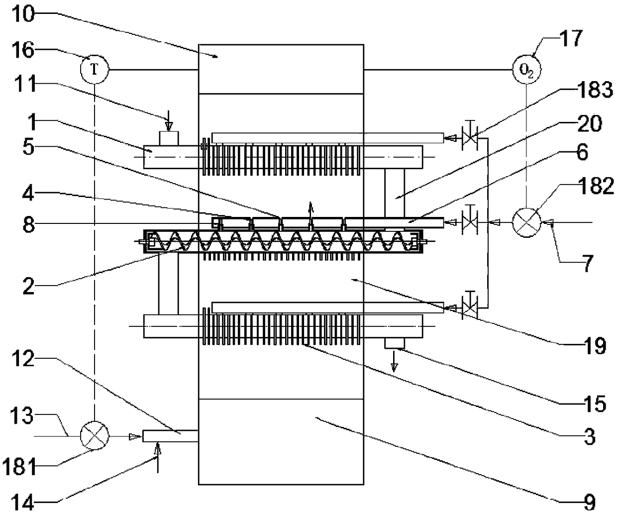
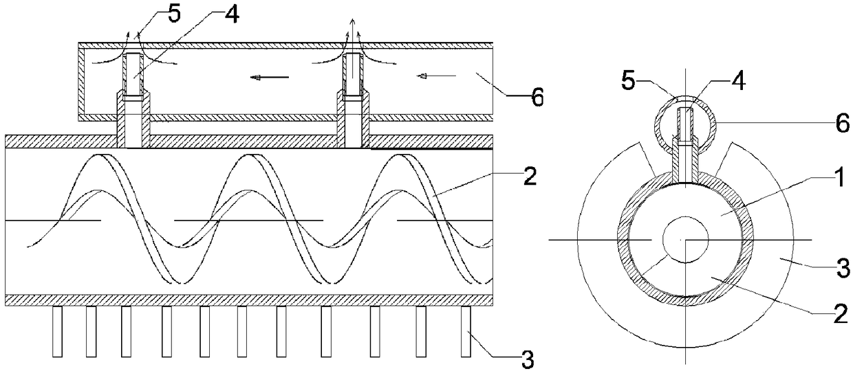
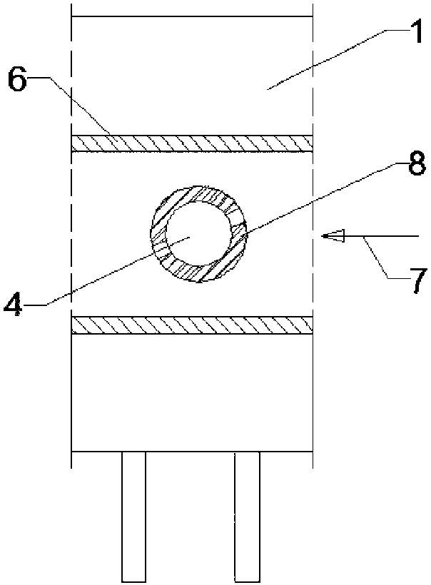
[0028]A wing-type sludge tube pyrolysis reactor, the reactor is composed of a pyrolysis furnace 19, a combustion chamber 9, and a flue gas mixing chamber 10, the bottom of the pyrolysis furnace 19 is connected to the combustion chamber 9, and the top of the pyrolysis furnace 21 is Connected with the flue gas mixing chamber 10, the combustion chamber 9 is equipped with a natural gas burner 12, the amount of natural gas is regulated by the temperature measuring and control instrument 16 installed on the flue gas mixing chamber 10, and the pyrolysis furnace 19 is equipped with at least 2 layers of pyrolysis Tube 1, both ends of each pyrolysis tube 1 extend out of the pyrolysis furnace 19 and are respectively provided with a mud inlet port and a mud outlet port, and the mud inlet port of the uppermost pyrolysis pipe is used as the mud inlet port of the reactor 11. The mud outlet port of the bottom pyrolysis tube 1 is used as the biochar outlet 15 of the reactor, and the mud outlet ...

Embodiment 2

[0031] A wing-type sludge tube pyrolysis reactor, consisting of a pyrolysis furnace 19, a combustion chamber 9, and a flue gas mixing chamber 10, the bottom of the pyrolysis furnace 19 is connected to the combustion chamber 9, and the top of the pyrolysis furnace 21 is connected to the flue gas The mixing chambers 10 are connected, the combustion chamber 9 is provided with a natural gas burner 12, the amount of natural gas is regulated by a temperature measuring and control instrument 16 arranged on the flue gas mixing chamber 10, and the pyrolysis furnace 19 is provided with a multilayer pyrolysis tube 1, each Both ends of each pyrolysis tube 1 extend out of the pyrolysis furnace 19. Outside the pyrolysis furnace 19, a mud inlet 11 is provided above one end of the uppermost layer of pyrolysis tube 1, and the bottom of the other end is connected to the upper and lower floor pyrolysis tubes. 20 is connected with the top of one end of the lower pyrolysis tube 1, and so on, the ot...

Embodiment 3

[0035] A new type of wing-type sludge tube pyrolysis reactor for municipal sludge disposal. The flue gas mixing chamber 10 is equipped with a heat transfer oil or steam heat exchanger and an air preheater. The flue gas is discharged after treatment. The heat of the heat conduction oil or steam heat exchanger is used to dry the wet sludge with 80% water content, so that the sludge moisture content in the sludge inlet 11 is below 20%, and the heat of the air preheater is used to heat the combustion air 14 and enter the hot air Inlet 7 air. The combustion chamber 9 is equipped with a diesel or heavy oil burner to ensure that the temperature of the flue gas mixing chamber 10 is 850°C, the temperature of the hot air inlet is 200°C, the oxygen content of the flue gas mixing chamber 10 is controlled at about 6%, and the fin ratio is 1.5 When compared with the light tube, the pyrolysis treatment capacity is about 15% higher.

[0036] Working process of the present invention is as fol...


PUM


Abstract

The invention relates to a wing type sludge pipe pyrolysis reactor. The reactor comprises a pyrolysis furnace, a combustion chamber and a flue gas mixing chamber, the bottom part of the pyrolysis furnace is connected with the combustion chamber, the top part of the pyrolysis chamber is connected with the flue gas mixing chamber, a natural gas nozzle is arranged on the combustion chamber, the amount of the natural gas is regulated by a temperature measurement and control instrument arranged on the flue gas mixing chamber, the pyrolysis furnace is internally provided with at least two layers ofpyrolysis tubes, the two ends of each pyrolysis tube both extend out of the pyrolysis furnace, a sludge feed port and a sludge discharge port are respectively arranged at the two ends of the pyrolysistube, the sludge feed port on the pyrolysis tube at the uppermost layer serves as a sludge inlet of the reactor, the sludge discharge port on the pyrolysis tube at the lowermost layer serves as a charcoal outlet of the reactor, the sludge discharge port on the pyrolysis tube at the upper layer among the adjacent pyrolysis tubes is connected with the sludge feed port on the pyrolysis tube at the lower layer among the adjacent pyrolysis tubes, the pyrolysis tube comprises a tube body, and the tube body is internally provided with a hollow spiral sheet. The whole system device produces the valuable charcoal in the process of the ultralow emission of pollutants.

Description

technical field [0001] The invention relates to a pyrolysis reactor for economically and efficiently treating sludge and producing biochar while realizing ultra-low pollutant discharge. Background technique [0002] Sludge is an inevitable by-product of sewage treatment. With the rapid development of economy, a severe situation of water environment and sludge siege has been formed in the world. Sludge contains a large amount of heavy metals, organic matter, etc., which is very harmful. The generation of a large amount of sludge has become an urgent problem for sewage treatment plants. Studies have shown that China produces 3 billion tons of sludge every year, and the European Union produces 5.48 billion tons of sludge every year. As a supporting field of water treatment, sludge disposal and related fields will undertake the important task of improving the environment. However, in reality, our disposal of sludge has not met the corresponding requirements. [0003] The cur...

Claims


Application Information

Patent Timeline
Patent Type & Authority Applications(China)
IPC IPC(8): C02F11/10C10B53/00
CPCC02F11/10C10B53/00Y02W10/40
Inventor 葛仕福周彩玲张程
Owner SOUTHEAST UNIV
Why Eureka
Try Eureka