
Fluid catalytic cracking (FCC) flue gas treatment system and FCC flue gas treatment method

A technology of flue gas and flue gas reheater, applied in the field of plume treatment, can solve the problems of high moisture content of waste residue, peeling off of anti-corrosion layer, acid corrosion, etc., achieve high surface area and density, reduce ammonia escape, and strong adsorption capacity Effect

Pending Publication Date: 2018-06-22
XIAMEN RECH TECH
View PDF10 Cites 1 Cited by
  • Summary
  • Abstract
  • Description
  • Claims
  • Application Information

AI Technical Summary

Problems solved by technology

[0007] SO in flue gas 3 It will lead to an increase in the acid dew point of the flue gas, and the flue gas temperature must be kept at 10-15°C higher than the acid dew point temperature to avoid acid corrosion of downstream equipment, which will lead to a decrease in the thermal efficiency of the unit; secondly, SO 3 NH that will not react with SCR denitrification in the air preheater 3 The reaction produces ammonium bisulfate, which will cause a large amount of fly ash to deposit on the surface of downstream equipment, causing equipment corrosion
[0008] (2) The existing wet desulfurization system cannot effectively remove SO 3 , producing a colored plume
[0011] (3) The waste water and waste residue produced by the desulfurization process after wet absorption of dust are difficult to handle
[0012] In the FCC regenerative flue gas wet absorption process, the catalyst particles in the flue gas will enter the desulfurization liquid, and the waste liquid needs to be discharged to the wastewater treatment system, and then discharged after oxidation, flocculation and filtration. The process is complicated and the operation stability is poor.
[0013] Filtration of fine dust in desulfurization waste liquid is a worldwide problem, and it is extremely difficult to meet the standard, and the filter device is easy to block, and regular backwashing will generate waste water, and the actual operation effect is not ideal
The waste residue generated during the wastewater treatment process has a high moisture content and is not easy to dispose of
[0014] (4) Particulate matter emission after wet desulfurization is difficult to meet the requirements of the new standard
It is difficult to meet the existing national and local particulate matter emission standards in the soot blowing stage of the catalytic cracking waste heat boiler
[0016] (5) The exhaust gas temperature is high, and the flue gas temperature changes greatly
[0017] After the FCC regeneration flue gas passes through the waste heat boiler, the normal temperature is 180-240°C, which has a large thermal impact on the anti-corrosion layer of the desulfurization system, which may easily cause the anti-corrosion layer to peel off.
[0018] In addition, when the high-temperature flue gas at the inlet of the desulfurization tower is combined with high-temperature flue gas spraying, a large number of fine particle crystals will be produced due to the heat exchange and evaporation of the slurry, causing a large amount of aerosol to enter the chimney with the flue gas, resulting in colored plume problems
Moreover, there is no effective treatment method for the above-mentioned colored plume in the prior art

Method used


Image

  • Fluid catalytic cracking (FCC) flue gas treatment system and FCC flue gas treatment method

Examples


Embodiment 1

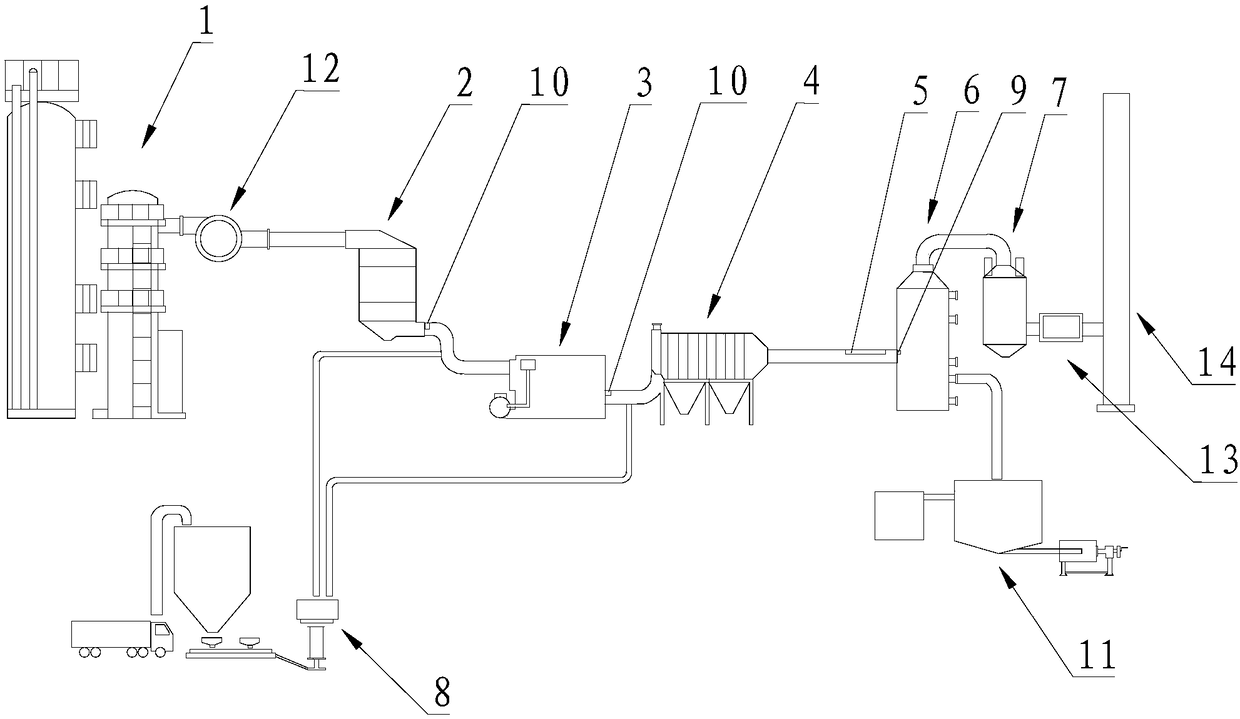
[0072] Please refer to figure 1 , Embodiment 1 of the present invention is:

[0073] The FCC flue gas treatment system of this embodiment includes an SCR reactor 2 (SCR is selective catalytic reduction), a waste heat boiler 3, a pre-dust collector 4, a water mist generating device 5, a wet desulfurization device 6, and a wet electrostatic precipitator. device 7, injection device 8, temperature detection device 9 and sulfur trioxide concentration detection device 10, the smoke inlet of the SCR reactor 2 is used to pass into the FCC flue gas to be treated (discharged from the FCC device 1, FCC is Fluid Catalytic Cracking, that is, catalytic cracking), the smoke outlet of the SCR reactor 2 and the smoke inlet of the waste heat boiler 3, the smoke outlet of the waste heat boiler 3 and the smoke inlet of the pre-dust collector 4, the The smoke outlet of the pre-dust collector 4 is connected to the smoke inlet of the wet desulfurization device 6, and the smoke outlet of the wet des...


PUM


Abstract

The invention relates to a fluid catalytic cracking (FCC) flue gas treatment system and an FCC flue gas treatment method. The system comprises a selective catalytic reduction (SCR) reactor, a waste heat boiler, a pre-dust remover, a water mist generator, a wet desulphurization device, a wet electrostatic precipitator, a jet apparatus, a temperature detection device and a sulfur trioxide concentration detection device, wherein a flue gas inlet of the SCR reactor is used for introducing FCC flue gas to be treated; a flue gas outlet of the SCR reactor is communicated with a flue gas inlet of thewaste heat boiler by means of a pipeline, a flue gas outlet of the waste heat boiler is communicated with a flue gas inlet of the pre-dust remover by means of a pipeline, a flue gas outlet of the pre-dust remover is connected with a flue gas inlet of the wet desulphurization device by means of a pipeline, and a flue gas outlet of the wet desulphurization device is communicated with a flue gas inlet of the wet electrostatic precipitator by means of a pipeline; a flue gas outlet of the wet electrostatic precipitator is used for discharging the treated FCC flue gas. The FCC flue gas treatment system and the FCC flue gas treatment method have the advantage of effectively treating colored smoke plume in the FCC flue gas.

Description

technical field [0001] The invention relates to smoke plume treatment technology, in particular to a treatment system and treatment method for FCC flue gas. Background technique [0002] The colored plume mainly refers to the fine dust, sulfate, ammonium salt, nitrate, heavy metal and other fine particles discharged into the atmosphere by the flue gas through the chimney. Due to the background color of the sky, sky light, viewing angle, etc., the white, gray, and yellow plumes are produced. , Blue tailing phenomenon. [0003] In FCC (Fluid Catalytic Cracking, catalytic cracking) regenerated flue gas, the sources of colored plume particulate matter mainly include the following ways: (1) particulate matter carried by the wear and tear of FCC regenerated catalyst; (2) escaped ammonia spray from SCR denitrification system NH 3 with SO 2 Ammonium sulfate crystals produced by combination; (3) sulfate produced by slurry crystallization at the tail of wet desulfurization chimney;...

Claims


Application Information

Patent Timeline
Patent Type & Authority Applications(China)
IPC IPC(8): B01D53/75B01D53/83B01D53/50B01D50/00F23J15/00F23J15/02F23J15/06F23J15/08
CPCB01D50/00B01D53/508B01D53/75B01D53/83F23J15/003F23J15/006F23J15/02F23J15/06F23J15/08F23J2215/20F23J2217/10B01D2251/304B01D2251/404B01D2258/0283Y02E20/30
Inventor 黄志超陈燕辉李尾阳
Owner XIAMEN RECH TECH
Learn More