Low-alloyed degradable miniature inner fixed assembly, magnesium alloy preparation method and magnesium alloy material

A technology of fixing components and magnesium alloys, applied in the direction of fixators, fastening devices, internal bone synthesis, etc., can solve the adverse effects of cell proliferation and osseointegration around bone screws, aggravated corrosion of pure magnesium, and decreased mechanical properties of bone screws, etc. problems, to achieve the effect of solving the problem of galvanic corrosion, low impurity content and low alloying element content

Pending Publication Date: 2018-07-03
西安卓恰新材料科技有限公司
0 Cites 10 Cited by

AI-Extracted Technical Summary

Problems solved by technology

The intensified corrosion of pure magnesium not only reduces the mechanical properties of bone scr...

Method used

As shown in Fig. 2 to Fig. 5, the present invention can prepare a kind of miniature internal fixation assembly through aforementioned preparation method and magnesium alloy material, comprise a bone plate 10 and a bone screw 20 correspondingly engaged in this bone plate 10 , the bone plate 10 includes a connecting bridge portion 11 and a plurality of fixing portions 12 respectively formed on both sides of the connecting bridge portion 11, each fixing portion 12 is annular and designed with a streamlined curved surface, each fixing portion 12 A fixation hole 13 is formed in the center, the number of fixation holes 13 on the bone plate 10 and the length of the middlemost connecting bridge part 11 can be adjusted, wherein, the increase of the thickest part of each fixing part 12 is 20% of the thickness of the connecting part ~32%, the thickened part connected between each fixing portion 12 and the connecting portion 11 is a streamlined curved surface with a smooth transition, preferably, the minimum width D2 of the connecting portion 11 is 40%-40% of the diameter D1 of each fixing portion 12 55.6%, to ensure a good fixation effect at the contact with the fracture suture. In this embodiment, the bone plate 10 is respectively provided with two fixation parts 12 on both sides of the connection part 11, and has four fixation holes in total. 13.
As shown in Figure 2, each fixed part 12 position thickness of this bone plate 10 increases, and the thickest part increment of each fixed part 12 is 32% of the thickness of this connecting part 11, and the thickened part is a smooth transition Streamlined curved surface, the outer contour of the bone plate 10 is a smooth transition surface, and the minimum width D2 of the connecting part 11 is 55.6% of the diameter D1 of each fixing part 12 to ensure a good fixing effect.
Compared with embodiment 1, magnesium alloy in embodiment 2 is by adjusting rolling process, adopts the method for synchronous rolling, has reduced the rolling process shear stress effect, and adopts the method for the multi-pass deformation of small amount of deformation , ultima...

Abstract

The invention discloses a low-alloyed degradable miniature inner fixed assembly, a magnesium alloy preparation method and a magnesium alloy material. The low-alloyed magnesium alloy material which ismicro in impurity content and low in degrading rate is obtained by means of the preparation methods of smelting, solution heat treatment and the like. Different strength and plasticity are matched bymeans of adjusting and rolling and post-rolling annealing process of the magnesium alloy material, so as to prepare medical implant miniature inner fixed assemblies which have different demands on strength and plasticity.

Application Domain

Technology Topic

Image

  • Low-alloyed degradable miniature inner fixed assembly, magnesium alloy preparation method and magnesium alloy material
  • Low-alloyed degradable miniature inner fixed assembly, magnesium alloy preparation method and magnesium alloy material
  • Low-alloyed degradable miniature inner fixed assembly, magnesium alloy preparation method and magnesium alloy material

Examples

  • Experimental program(5)
  • Comparison scheme(1)
  • Effect test(1)

Example Embodiment

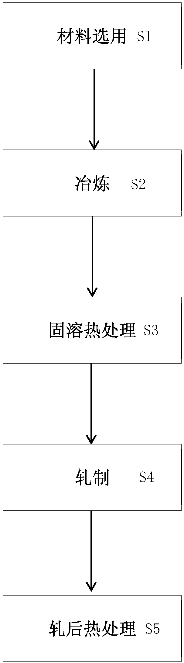
[0044] Such as figure 1 As shown, the present invention is a low alloying and degradable micro internal fixation component, a magnesium alloy preparation method and a magnesium alloy material. The magnesium alloy preparation method includes material selection S1, smelting S2, solution heat treatment S3, rolling S4, post-rolling heat treatment S5 and other steps.
[0045] Material selection step S1: Use pure magnesium ingots with a purity of greater than 99.99% as the magnesium raw material, use zinc granules with a purity of greater than 99.9% as the zinc raw material, and use a magnesium-calcium intermediate alloy with a purity of more than 99.99% as the calcium raw material to prepare calcium (Ca) The mass fraction is 0.01%~0.1%, the mass fraction of zinc (Zn) is 0.8%~2.5%, and the rest is magnesium. The single content of impurities such as aluminum, iron, copper, manganese, silicon, and nickel does not exceed 0.005%, and the total content of impurities does not exceed 0.01 % Magnesium alloy material.
[0046] Smelting step S2: The smelting process includes smelting under high vacuum, assisting mechanical stirring and filtering methods to reduce the impurity content, refine the structure, and reduce the internal defects of the ingot.
[0047] The specific method adopted in the present invention is as follows: the pure magnesium ingot (magnesium mass fraction greater than 99.99%) and magnesium (Mg)-calcium (Ca) master alloy (calcium (Ca) mass fraction 1.8 to 6%) in a volume fraction of 5% It is cleaned in the hydrochloric acid and ethanol solution to remove the surface oxide layer, dried under an argon protective atmosphere, placed in a graphite crucible, and pure zinc particles (zinc mass fraction greater than 99.9%) are placed in the secondary feeding hopper. Evacuate until the vacuum degree of the vacuum furnace is lower than 0.01Pa, and then fill with high-purity argon until the vacuum pressure gauge shows -0.03~-0.08MPa. After the furnace is charged twice, the raw materials in the crucible are heated, and the pure magnesium ingot is to be cast. After the financialization of Hezhonghe, open the secondary hopper at 690 to 730 degrees to add zinc, turn on the mechanical stirring, the stirring frequency is 50 to 250 revolutions per minute, and the stirring time is 1 to 5 minutes to fully alloy the liquid. After the alloy melt is filtered by a filtering device, it is poured into a pre-baked cast iron mold at a temperature of 700-750 degrees, and it is naturally cooled to room temperature for demoulding.
[0048] Among them, the as-cast structure of the magnesium alloy is α-Mg and the second phase. The form of the second phase is granular, distributed in grain boundaries or inside grains. The second phase is MgZn phase with Ca solid solution or Mg with Ca solid solution 2 Zn 3 phase.
[0049] Solution heat treatment step S3: Use a box-type resistance furnace to perform solution heat treatment on the ingot under an argon protective atmosphere, the temperature is 350-500 degrees, the holding time is 12 to 48 hours, after the heat preservation is completed, room temperature pure water quenching to form an alloy ingot .
[0050] Rolling step S4: After the aforementioned solution heat treatment step, the alloy ingot undergoes surface processing, and the outer oxide scale and casting defects are removed by mechanical processing. The surface is polished with sandpaper and kept in a box-type resistance furnace for 30 minutes at a temperature of 400~ 450 degrees.
[0051] The rolling means can be rolled by synchronous rolling, asynchronous rolling or cross rolling. The roll speed is less than 245mm/s, and the roll preheating temperature is 100 degrees. The rolling adopts a small deformation multi-pass processing method, the initial rolling pass processing rate is less than 10%, the intermediate rolling pass processing rate is 10-30%, and the final rolling pass processing rate is 30% to 70%. The total rolling deformation is greater than 80%. Keep warm for 10-30 minutes between passes at 400-450 degrees.
[0052] Post-rolling heat treatment step S5: annealing is performed after the rolling is completed, the temperature is 300 degrees, the temperature is kept for 10 minutes to 1.5 hours, and the magnesium alloy material prepared by the preparation method of the present invention can be obtained by water quenching at room temperature after taking it out.
[0053] The mechanical properties of the magnesium alloy material obtained by the foregoing preparation method of the present invention can meet the following requirements: the magnesium alloy material used as a bone plate has a tensile strength of greater than 200 MPa in the rolling direction, a yield strength of greater than 150 MPa, and an elongation after fracture greater than 25 %, the reduction of area is greater than 25%; the magnesium alloy material used as a bone screw has a tensile strength greater than 250MPa along the rolling direction, a yield strength greater than 200MPa, an elongation after fracture greater than 10%, and a reduction of area greater than 10%. The degradation rate of magnesium alloy material in vitro is less than 3mm/year.
[0054] Such as Figure 2 to Figure 5 As shown, the present invention can prepare a miniature internal fixation component by the aforementioned preparation method and magnesium alloy material, including a bone plate 10 and a corresponding bone screw 20 joined to the bone plate 10, and the bone plate 10 includes a connecting bridge Part 11 and a plurality of fixing parts 12 respectively formed on both sides of the connecting bridge part 11. Each fixing part 12 is annular and has a streamlined curved surface design. A fixing hole 13 is formed in the center of each fixing part 12 to connect bones. The number of fixing holes 13 on the board 10 and the length of the middle connecting bridge 11 can be adjusted. The thickest part of each fixing part 12 increases by 20% to 32% of the thickness of the connecting part. The thickened part connected by the connecting portion 11 is a smooth transition of streamlined curved surfaces. Preferably, the minimum width D2 of the connecting portion 11 is 40% to 55.6% of the diameter D1 of each fixing portion 12 to ensure contact with the fracture joint In this embodiment, the bone plate 10 is provided with two fixing portions 12 on both sides of the connecting portion 11, and there are four fixing holes 13 in total.
[0055] The bone screw 20 can correspondingly penetrate into each fixing hole 13 of the bone plate 10. The bone screw 20 has a flat top surface 21 and a contact surface 22 surrounding and connected to the top surface 21 of the nail cap. The contact surface 22 enables the bone screw 20 and the bone plate 10 to contact and fit smoothly. A threaded portion 23 extends downward from the contact surface 22. The top surface of the nail cap 21 is further formed with a groove 24. The groove 24 is cylindrical with a diameter of 1.2mm and a depth of 0.4mm. The purpose of the groove 24 is not to rotate and tighten the screw, but to Realize the close fit with the screwdriver bit to reduce the risk of screw falling during the operation. Around the top surface 21 of the nail cap, four surrounding screw grooves 25 are formed. The design of the screw grooves 25 provides the torque of the screwdriver bit to realize the vertical screwing of the screw.
[0056] Preferably, in order to achieve a tight fit between the groove 24 and the screwdriver bit, the tolerance between the groove 24 and the screwdriver bit is along the diameter direction, with a positive tolerance of 0.02 mm and a negative tolerance of 0. The cylinder on the screwdriver bit matches the shape of the groove 24, and the design size is also 1.2mm in diameter, with a positive tolerance of 0.02mm, and a negative tolerance of 0. Such a design can ensure that after the screwdriver bit is inserted into the bone screw 20, the bone screw 20 is lifted upside down and the screwdriver does not fall. This effectively solves the risk of the bone screw 20 falling from the screwdriver during the operation. At the same time, when the bone screw 20 is used in conjunction with the bone plate 10, it can reduce the stress concentration of each fixing hole 13 and the bone screw 20 in the miniature internal fixation assembly when the force interferes, so as to increase the system strength of the plate screw combination part. Avoid excessive stress corrosion.

Example Embodiment

[0057] Example 1
[0058] The raw material configuration is based on the following alloy raw materials: magnesium ingots with a purity of greater than 99.99% are used as the magnesium raw materials, magnesium with a purity of greater than 99.99% -5.97% calcium master alloy (Mg-Ca) as the calcium raw material, and zinc with a purity of more than 99.9% Granules are used as zinc raw materials.
[0059] The smelting process is as follows: the pure magnesium ingot and Mg-Ca master alloy are cleaned in a 5% hydrochloric acid ethanol solution to remove the surface oxide layer, dried under an argon protective atmosphere, and placed in a graphite crucible. Pure zinc particles Put it into the secondary feeding hopper. Evacuate until the vacuum degree of the vacuum furnace is lower than 0.01Pa, and then fill with high-purity argon until the vacuum pressure gauge shows -0.03MPa. After the furnace is inflated and washed twice, the raw materials in the crucible are heated. After the magnesium ingot and the intermediate are financialized , Open the secondary hopper at 705 degrees to add zinc, turn on mechanical stirring, stirring frequency 60 rpm, stirring time 3 minutes, so that the liquid is fully alloyed. After the alloy melt is filtered by a filtering device, it is poured into a pre-baked cast iron mold at a temperature of 720 degrees, and it is naturally cooled to room temperature and demolded to obtain the first ingot.
[0060] The alloy composition of the first ingot was analyzed by ICP-AES, and the analysis results are described in Table 1.
[0061] Use box-type resistance furnace under the protection of argon to perform solution heat treatment on the first ingot at a temperature of 400°C and a holding time of 20 hours; after the holding is completed, water quenching at room temperature is used to ensure that the alloying elements exist as supersaturated solid solutions as much as possible In the magnesium matrix, reduce the number of second phases in the alloy. Next, use a machine tool to peel the surface until there are no visible shrinkage holes, pores, inclusions and other casting defects on the surface to obtain the second ingot. Use a scanning electron microscope to observe the cross-sectional morphology of the second ingot, and the results are as follows Figure 6A Shown.
[0062] The second ingot is kept at 450 degrees in a box-type resistance furnace for 30 minutes, and the 22.45mm thick ingot is rolled into a plate with a thickness of 1.45mm through 16 passes using asynchronous rolling, with a total deformation of 93.5%. Differential speed ratio of asynchronous rolling is 1:1.1, the heat is kept at 450 degrees between passes for 10 to 20 minutes, the processing rate of 1 to 4 passes is 2% to 3%, and the processing rate of 5 to 8 passes is 5 % To 6%, the processing rate of 9 to 14 passes is 9% to 25%, and the processing rate of the last two passes is 50%.
[0063] The rolled plate is annealed at 300 degrees for 30 minutes in the resistance furnace, and then water quenched at room temperature after being taken out. The metallographic analysis of the annealed sheet along the rolling surface, the results are as follows Figure 7A Shown.
[0064] The magnesium alloy has a uniform structure, complete recrystallization, a small amount of twins inside the crystal grains, and an average crystal grain size of 8.2 microns.
[0065] A room temperature tensile test of metallic materials was used to measure the mechanical properties of the plates, and the analysis results were recorded in Table 2.
[0066] Using simulated body fluids for 2 weeks, the in vitro degradation rate of the degradable magnesium alloy material is 2.22 mm/year.
[0067] The magnesium alloy described in Example 1 has medium strength and good plasticity, so the magnesium alloy is processed into figure 2 The four-hole bone plate with a thickness of 0.6mm is shown.
[0068] Such as figure 2 As shown, the thickness of each fixing part 12 of the bone plate 10 is increased, the thickest part of each fixing part 12 is increased by 32% of the thickness of the connecting part 11, and the thickened part is a smooth transitional streamlined curved surface. The outer contour of 10 is a smooth transition surface, and the minimum width D2 of the connecting portion 11 is 55.6% of the diameter D1 of each fixing portion 12 to ensure a good fixing effect.
[0069] A 4mm radius clamp is used to perform repeated bending experiments on the bone plate 10, and no fracture occurs after bending more than 10 times, which meets the requirement of shaping the bone plate to fit the surgical site during maxillofacial repair surgery.

Example Embodiment

[0070] Example 2
[0071] The raw material configuration is first based on the following alloy raw materials: magnesium ingots with a purity of greater than 99.99% as the magnesium raw materials, magnesium with a purity of greater than 99.99%-2.6% calcium master alloy (Mg-Ca) as the calcium raw material, and zinc with a purity of greater than 99.9% Granules are used as zinc raw materials.
[0072] The smelting process is as follows: the pure magnesium ingot and (Mg-Ca) master alloy are cleaned in a 5% hydrochloric acid ethanol solution to remove the surface oxide layer, dried in an argon atmosphere, and placed in a graphite crucible. The zinc granules are put into the secondary feeding hopper. Evacuate until the vacuum degree of the vacuum furnace is lower than 0.01Pa, and then fill with high-purity argon until the vacuum pressure gauge shows -0.03MPa. After the furnace is inflated and washed twice, the raw materials in the crucible are heated. After the magnesium ingot and the intermediate are financialized , Open the secondary hopper at 700 degrees to add zinc, turn on mechanical stirring, stirring frequency 60 rpm, stirring time 3 minutes, so that the liquid is fully alloyed. After the alloy melt is filtered by a filter device, it is poured into a pre-baked cast iron mold at a temperature of 750 degrees, and it is naturally cooled to room temperature and demolded to obtain the first ingot.
[0073] The alloy composition of the first ingot was analyzed by ICP-AES, and the analysis results are described in Table 1.
[0074] Use box-type resistance furnace under the protection of argon to conduct solution heat treatment on the first ingot at a temperature of 450°C and a holding time of 16 hours; after the holding is completed, water quenching at room temperature is used to ensure that the alloy elements exist as supersaturated solid solutions as much as possible In the magnesium matrix, reduce the number of second phases in the alloy. Next, use a machine tool to peel the surface until there are no visible shrinkage holes, pores, inclusions and other casting defects on the surface to obtain the second ingot. Use a scanning electron microscope to observe the cross-sectional morphology of the second ingot, and the results are as follows Figure 6B Shown.
[0075] The second ingot is kept at 450 degrees in a box-type resistance furnace for 30 minutes, and the 23.85mm thick ingot is rolled into a 2.73mm thick plate through 17 passes in a synchronous rolling method, with a total deformation of 88.6%. The temperature is kept at 450 degrees between synchronous rolling passes for 10 to 15 minutes, and the rolling speed is 0.1 to 0.2m/s. The processing rate for the first 7 passes is 1% to 5%, the processing rate for passes 8 to 12 is 5% to 7%, and the processing rate for passes 13 to 15 is 12% to 15.7%. The processing rates of the last two passes were 28.1% and 53.7%, respectively.
[0076] The rolled plate is annealed at 300 degrees for 30 minutes in the resistance furnace, and then water quenched at room temperature after being taken out. The metallographic analysis of the annealed sheet along the rolling surface, the results are as follows Figure 7B Shown.
[0077] The magnesium alloy has a uniform structure, incomplete recrystallization, a small amount of twin crystals in the crystal grains, and a non-dynamic recrystallization area, with an average crystal grain size of 6.2 microns.
[0078] A room temperature tensile test of metallic materials was used to measure the mechanical properties of the plates, and the analysis results were recorded in Table 2.
[0079] Compared with Example 1, the magnesium alloy in Example 2 reduces the shear stress during the rolling process by adjusting the rolling process and adopts the synchronous rolling method, and adopts the method of small deformation and multi-pass deformation. Reduce the amount of rolling deformation in a single pass. The occurrence of dynamic recrystallization requires the amount of strain to reach a critical strain. The reduction of the amount of deformation leads to a decrease in the rate of dynamic recrystallization, and there are areas of non-dynamic recrystallization in the material structure to keep the material high in strength. Therefore, a magnesium alloy material with high strength and low plasticity or low strength and high plasticity can be obtained by adjusting the amount of rolling deformation.
[0080] Using simulated body fluids for 2 weeks, the in vitro degradation rate of the degradable magnesium alloy material is 1.99 mm/year.
[0081] The magnesium alloy described in Example 2 has higher strength and lower plasticity, and can be processed into Figure 4 The bone screws shown are used with the corresponding bone plates. Considering that the difference in alloy composition will cause contact corrosion, the bone screw in Example 2 needs to be used with a bone plate of similar composition.
[0082] The bone plates described in Example 1 and the bone screws described in Example 2 were implanted in the mandibles of miniature pigs. One month after the operation, neither the bone plates nor the bone screws were significantly degraded, and no obvious air bubbles were generated around the implants. There was no inflammatory reaction at the surgical site, and the fracture line healed well. After three months of implantation, the joint between the bone plate and the bone screw was degraded, but the fixation of the nail plate system remained good. The average degradation rate of bone plates in vivo is 0.13mm/year, and the average degradation rate of bone screws in vivo is 0.15mm/year.

PUM

PropertyMeasurementUnit
Tensile strength>= 200.0mPa
Yield strength>= 150.0mPa
Tensile strength>= 250.0mPa
tensileMPa
Particle sizePa
strength10

Description & Claims & Application Information

We can also present the details of the Description, Claims and Application information to help users get a comprehensive understanding of the technical details of the patent, such as background art, summary of invention, brief description of drawings, description of embodiments, and other original content. On the other hand, users can also determine the specific scope of protection of the technology through the list of claims; as well as understand the changes in the life cycle of the technology with the presentation of the patent timeline. Login to view more.

Similar technology patents

Preparation method of graphene material and graphene material

InactiveCN108033441ALow impurity contentHigh quality structureGrapheneGrapheneMaterials science
Owner:SICHUAN JUCHUANG SHIMOXI TECH CO LTD

Ferrite antibacterial stainless steel for low-chrome copper-containing dishware and manufacturing method thereof

ActiveCN1827824AExcellent long-lasting antibacterial effectLow content of alloying elementsTemperature control deviceHeat treatment process controlPre treatmentChromium
Owner:SHANXI TAIGANG STAINLESS STEEL CO LTD

Classification and recommendation of technical efficacy words

  • Low content of alloying elements
  • Low impurity content
Why Eureka
Try Eureka