Counter-flow moving bed filter unit

A moving bed and filter technology, applied in chemical instruments and methods, gas treatment, membrane technology, etc., can solve problems such as incomplete combustion, smoke emission pollution, ecosystem damage, etc., to prevent back-mixing and carryover, improve Effect of removal rate and high removal rate

Inactive Publication Date: 2018-09-11
ZHEJIANG UNIV
View PDF2 Cites 8 Cited by
  • Summary
  • Abstract
  • Description
  • Claims
  • Application Information

AI Technical Summary

Problems solved by technology

[0003] However, the heat treatment technology of domestic waste has serious problems of flue gas emission pollution. The more prominent one is that due to the complex composition of urban domestic waste, compared with traditional fuels such as coal, it contains a large amount of PVC-based high-chlorine resin as the main source of organic chlorine. Plastic and rubber household garbage, and some kitchen waste household garbage with sodium chloride as the main source of inorganic chlorine, therefore, in the process of thermal treatment of household garbage, in addition to nitrogen and sulfur pollutants, the raw materials contain a large amount of chlorine The characteristics of the incineration will also lead to a large amount of HCl in the exhaust of the incineration flue gas. The discharge of hydrogen chloride will directly lead to the formation of acid rain and cause serious damage to the ecosystem. Moreover, hydrogen chloride pollutants also have a strong acid corrosion effect on the furnace equipment. In addition, A certain amount of fly ash will be produced during the thermal treatment of municipal solid waste, which contains incompletely burned carbon particles and metal catalysts (transition state metals), which will undergo chlorination and condensation reactions w

Method used


Image

  • Counter-flow moving bed filter unit

Examples


Embodiment Construction

[0022] The present invention will be further described below in conjunction with drawings and embodiments.

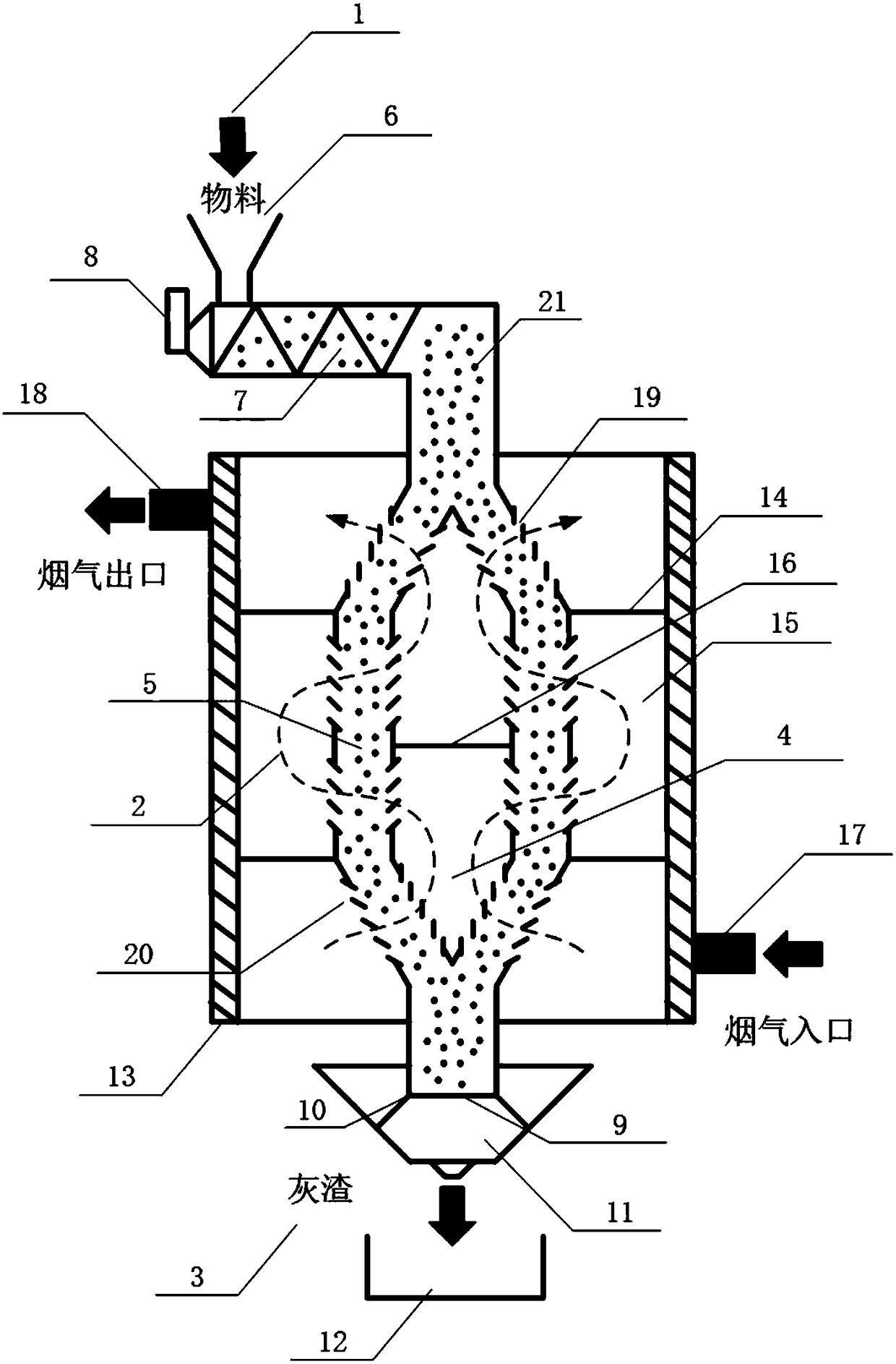
[0023] Such as figure 1 As shown, the specific implementation of the present invention includes a feeding system 1, a catalytic adsorption chamber 2, and a slag removal system 3. The catalytic adsorption chamber 2 is mainly composed of a flue gas inner chamber circulation chamber 4, a bed material filling chamber 5 and a flue gas outer chamber circulation chamber 15. Composition, the catalytic adsorption chamber 2 has a double-tube structure, the inner tube is the flue gas inner chamber circulation chamber 4, the outer cylinder is the flue gas outer chamber circulation chamber 15, the bed material filling chamber 5 is between the outer cylinder and the inner cylinder, and the catalytic adsorption chamber The upper part of the bed material filling chamber 5 of 2 is equipped with a connection feeding system 1, and the outlet of the lower end of the bed material filling ch...


PUM


Abstract

The invention discloses a counter-flow moving bed filter unit, which comprises a feeding system, a catalytic adsorption chamber and a deslagging system. The catalytic adsorption chamber is mainly composed of a flue gas internal-cavity circulation chamber, a bed material filling chamber and a flue gas external-cavity circulation chamber. The catalytic adsorption chamber is shaped in a double-cylinder structure: the inner cylinder is the flue gas internal-cavity circulation chamber, and the outer cylinder is the flue gas external-cavity circulation chamber. The bed material filling chamber is arranged between the outer cylinder and the inner cylinder. The upper part of the bed material filling chamber of the catalytic adsorption chamber is connected with the feeding system. A lower outlet ofthe bed material filling chamber of the catalytic adsorption chamber is provided with the deslagging system. The bottom of the flue gas external-cavity circulation chamber is provided with a flue gasinlet, and the top of the flue gas external-cavity circulation chamber is equipped with a flue gas outlet. The filter unit of the invention has advantages of simple structure, uniform flue gas flow velocity and wide application range, and especially can be used to directly purify high-temperature flue gas, thus providing favorable conditions for waste heat utilization and cooling equipment.

Description

technical field [0001] The invention relates to a filter in the technical field of dusty flue gas treatment equipment, in particular to a countercurrent moving bed filter device, which is suitable for treating high temperature, strong corrosion, many types of pollutants, and large changes in processing capacity. All kinds of dusty flue gas, especially complex domestic waste incineration flue gas. Background technique [0002] With the rapid development of my country's social economy, the amount of municipal solid waste generated and removed increases year by year. A large amount of waste not only occupies a large amount of valuable land resources, but also poses a huge threat to the ecological environment and human health. The acceleration of urbanization has made the disposal of urban domestic waste a very difficult problem. At present, the disposal technologies of domestic waste mainly include landfill, fermentation, composting and heat treatment, including incineration, p...

Claims


Application Information

Patent Timeline
IPC IPC(8): B01D53/68B01D53/83B01D53/86B01D53/72B01D53/08
CPCB01D53/08B01D53/685B01D53/83B01D53/8668B01D2251/304B01D2251/404B01D2251/602B01D2251/606B01D2253/102B01D2255/2047B01D2255/207B01D2255/20738B01D2255/20753B01D2255/50B01D2257/2045B01D2257/7022
Inventor 黄群星胡斌航池涌严建华李晓东蒋旭光马增益王飞陆胜勇金余其
Owner ZHEJIANG UNIV
Why Eureka
Try Eureka