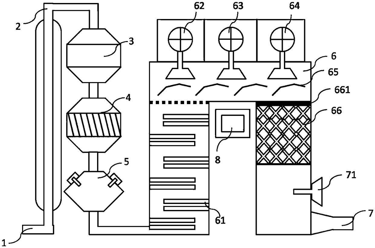
Intelligent flue gas denitration equipment
A denitrification and equipment technology, applied in the field of intelligent flue gas denitrification equipment, can solve the problems of inability to enter the liquid medium and difficult microbial transformation, and achieve the effects of saving manpower and material resources, high degree of equipment mechanization, and low energy consumption
- Summary
- Abstract
- Description
- Claims
- Application Information
AI Technical Summary
Problems solved by technology
Method used
Image
Examples
Embodiment 1
[0019] Such as figure 1 As shown, the intelligent flue gas denitrification device of the present invention includes a flue gas inlet 1, the flue gas inlet is provided with a first gas analyzer, the flue gas inlet is connected to a flue gas pipe 2, and the other end of the flue gas pipe A dedusting unit 3 is connected, a desulfurization unit 4 is connected under the dedusting unit 3, an ammonia spray unit 5 is connected under the desulfurization unit 4, and the ammonia spray unit 5 includes an injection system and an ammonia injection system, The injection system is connected to the ammonia injection system, the ammonia spray unit 5 is a vortex static mixing spray grid, the ammonia spray unit 5 is connected to the denitrification unit 6 through a flue pipe, and the denitrification unit 6 is an n-type cylindrical structure, and one end of the desulfurization unit 6 is provided with an SCR reactor 61, and the SCR reactor 61 includes a rod-shaped heating system vertically fixed on...
Embodiment 2
[0023] The ammonia injection system includes the ammonia injection system including the ammonia evaporator, the ammonia buffer tank, the ammonia dilution tank, the wastewater pump, and the liquid ammonia in the wastewater tank storage tank is transported to the evaporator by self-pressure, and in the evaporator (heated by steam) Evaporate ammonia, each evaporation tank is equipped with a pressure control valve to control the pressure of ammonia to ≤2kg / cm 2 . When the outlet pressure exceeds 2kg / cm 2 , cut off the throttle valve and stop the supply of liquid ammonia. The ammonia stream evaporated from the evaporation tank enters the ammonia buffer tank, and is sent to the spray system of the ammonia spray unit through the ammonia delivery pipeline, and then dilutes the high-concentration anhydrous ammonia with air, so that the ammonia / air mixture is safe and non-flammable .
[0024] The heat required for the evaporation of liquid ammonia is provided by low-pressure steam, a...
Embodiment 3
[0031] To prepare high-efficiency activated carbon, cut waste tires into 1cm*1cm pieces, rinse the pieces with distilled water, and dry them at 105°C for 3 hours, then heat the pieces to 300°C to remove liquids other than carbon-containing components to obtain the first For the reactant, the first reactant is mixed with hydrogen peroxide and heated to 500°C in a muffle furnace for full carbonization, and the heating is carried out for 4 hours to obtain the second reactant. The second reactant was thoroughly rinsed with distilled water and dried, and the dried second reactant was activated at 900 °C for 5 hours, and then the resulting second reactant was rinsed with distilled water and dried to obtain the first activated carbon, which was washed with 4M HNO 3 Activate the first activated carbon (1g activated carbon / 10ml HNO 3 ) The reaction condition is 55°C, the reaction is carried out in a reflux condenser for 4 hours, and then the product is washed with distilled water and d...
PUM
 Abstract
Description
Claims
Application Information
 - R&D Engineer
- R&D Manager
- IP Professional
- Industry Leading Data Capabilities
- Powerful AI technology
- Patent DNA Extraction
Browse by: Latest US Patents, China's latest patents, Technical Efficacy Thesaurus, Application Domain, Technology Topic, Popular Technical Reports.
© 2024 PatSnap. All rights reserved.Legal|Privacy policy|Modern Slavery Act Transparency Statement|Sitemap|About US| Contact US: help@patsnap.com


