Hazardous waste high-temperature melting microcrystal purification device and tail gas purification method

A high-temperature melting and purification device technology, which is applied in the direction of combustion methods, incinerators, lighting and heating equipment, etc., can solve problems such as inability to achieve reduction, large floor space, and excessive heavy metals

Inactive Publication Date: 2019-01-04
HARBIN INST OF TECH
View PDF4 Cites 18 Cited by
  • Summary
  • Abstract
  • Description
  • Claims
  • Application Information

AI Technical Summary

Problems solved by technology

[0003] At present, the main disposal method of hazardous waste is chelation landfill, which has the following disadvantages: it occupies a large area, cannot achieve reduction, harmlessness a

Method used


Image

  • Hazardous waste high-temperature melting microcrystal purification device and tail gas purification method
  • Hazardous waste high-temperature melting microcrystal purification device and tail gas purification method
  • Hazardous waste high-temperature melting microcrystal purification device and tail gas purification method

Examples


specific Embodiment approach 1

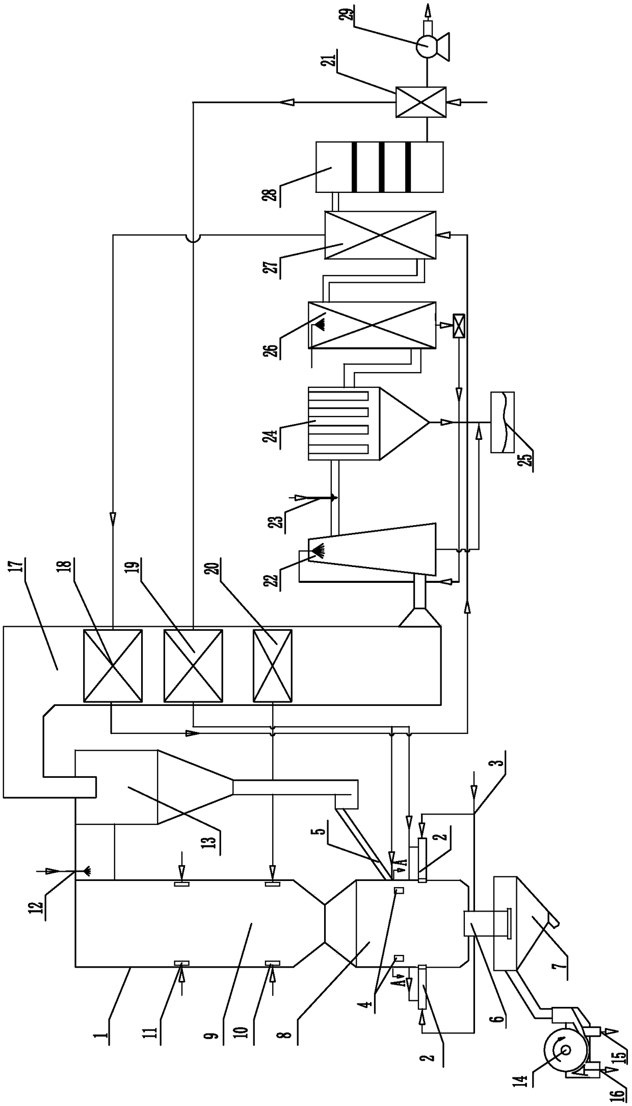
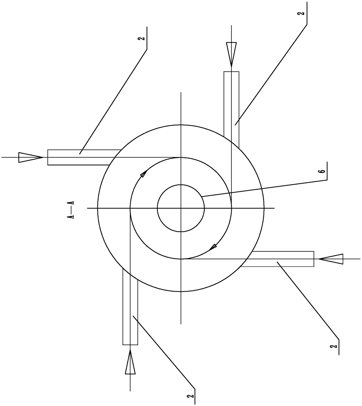
[0024] Specific implementation mode one: as figure 1 , figure 2As shown, this embodiment discloses a hazardous waste high-temperature melting microcrystal purification device, which consists of a melting furnace body 1, a gas pipeline 3, a material return port 5, a slag discharge port 6, a molten slag water quenching pool 7, a secondary Air nozzle 10, recirculation flue gas nozzle 11, SNCR urea nozzle 12, cyclone separator 13, magnetic separator 14, microcrystalline raw material slag outlet 15, heavy metal outlet 16, tail flue 17, thermal oil economizer 18, High temperature air preheater 19, medium temperature air preheater 20, low temperature air preheater 21, cooling tower 22, slaked lime and activated carbon nozzle 23, bag filter 24, secondary ash bin 25, wet flue gas purification device 26, Flue gas heater 27, SCR denitrification device 28, induced draft fan 29, four burners 2 and four feeding ports 4;

[0025] The melting furnace body 1 is composed of a melting chamber...

specific Embodiment approach 2

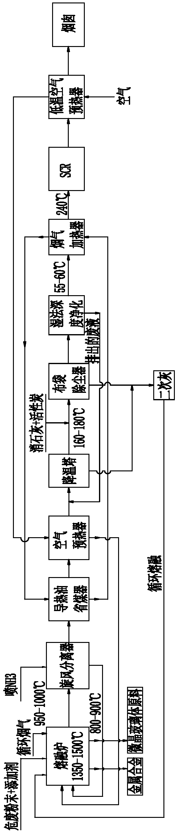
[0026] Specific implementation mode two: as Figure 1-Figure 3 As shown, this embodiment discloses a method of using the device described in Embodiment 1 to realize the purification of hazardous waste high-temperature molten microcrystals and tail gas purification. The steps of the method are as follows:

[0027] Step 1: Mix the powder of hazardous waste to less than 0.1mm into nucleating agent and flux. The weight of nucleating agent used accounts for 3-5% of the weight of hazardous waste, and the proportion of flux used is less than 10% of the weight of hazardous waste. Mix The final hazardous waste material is sent into the melting chamber 8 through the feed port 4;

[0028] Step 2: The hot primary air and gas preheated by the high-temperature air preheater 19 are sent tangentially into the melting chamber 8 through the burner 2 to form vortex combustion, and the hazardous waste powder fed in is rapidly heated to a molten state, and the melting chamber The temperature insi...

specific Embodiment approach 3

[0033] Specific embodiment three: This embodiment is a further description of specific embodiment two. In step one, the nucleating agent is Fe 2 o 3 、TiO 2 or P 2 o 5 , the flux is SiO 2 , CaO or glass slag.


PUM


Abstract

The invention belongs to the field of hazardous waste treatment, and relates to a hazardous waste high-temperature melting microcrystal purification device and a tail gas purification method. Combustors and feeding openings are arranged on the side wall of a melting chamber. The combustor is connected with a gas pipeline and a high-temperature air preheater. A molten slag water quenching pool below the melting chamber is connected with a magnetic separator. A secondary air nozzle and a circulating flue gas nozzle are arranged on the lower portion of a secondary combustion chamber. An outlet ofa melting furnace is connected with a cyclone separator. The melting chamber on the lower portion is connected with a material return opening. An SNCR urea nozzle is arranged at an inlet of the cyclone separator, and an outlet of the cyclone separator is connected with a tail flue. A heat conduction oil economizer, the high-temperature air preheater and a medium-temperature air preahter are arranged in the tail flue. A flue gas outlet is connected with a cooling tower, a slaked lime and activated carbon sprayer, a cloth bag dust remover, a wet flue gas purification device, a flue gas heater,an SCR denitration device and a low-temperature air preheater. A waste liquid outlet of the wet flue gas purification device is connected with the cooling tower. The heat conduction oil economizer isconnected with the flue gas heater. The hazardous waste high-temperature melting microcrystal purification device is used for hazardous waste melting microcrystal purification.

Description

technical field [0001] The invention belongs to the field of hazardous waste treatment, and in particular relates to a hazardous waste high-temperature melting microcrystal purification device and a tail gas purification method. Background technique [0002] With the rapid development of my country's industry, the hazardous waste discharged in the process of industrial production is increasing day by day. Hazardous wastes such as metallurgical solid waste, chemical fertilizer solid waste, electroplating sludge, chemical sludge, and garbage fly ash contain a large amount of heavy metals and dioxins, which pose a major safety hazard to the environment. How to properly dispose of these hazardous wastes has become an urgent problem in the field of environmental protection. [0003] At present, the main disposal method of hazardous waste is chelation landfill, which has the following disadvantages: it occupies a large area, cannot achieve reduction, harmlessness and recycling, a...

Claims


Application Information

Patent Timeline
IPC IPC(8): F23G7/00F23G5/44F23J15/02F23J15/04F23J15/06
CPCF23G5/44F23G7/00F23J15/025F23J15/04F23J15/06
Inventor 别如山陈佩
Owner HARBIN INST OF TECH
Why Eureka
Try Eureka