
Optical temperature measuring material with color-change fluorescence, and preparation method and application thereof

An optical temperature measurement and fluorescence technology, which is applied in the field of fluorescent color-changing optical temperature measurement materials and its preparation, can solve the problems of unsatisfactory effect and poor energy level, and achieve the effects of stable properties, wide temperature measurement range and high relative sensitivity

Inactive Publication Date: 2019-01-29
UNIV OF SHANGHAI FOR SCI & TECH
View PDF6 Cites 12 Cited by
  • Summary
  • Abstract
  • Description
  • Claims
  • Application Information

AI Technical Summary

Problems solved by technology

[0003] However, the temperature measurement sensitivity is proportional to the energy level difference of the thermally coupled energy levels
Therefore, the effect of improving the temperature measurement sensitivity by simply looking for a larger "thermal coupling energy level" energy level difference is not ideal. At the same time, the temperature measurement sensitivity is proportional to the energy level difference of the thermal coupling energy level. Limitations of Level Fluorescence Intensity Ratio for Temperature Sensing
Therefore, the thermal coupling conditions limit the further improvement of the detection sensitivity and signal detection discrimination of the fluorescence intensity ratio of the thermal coupling energy level of a single rare earth luminescent ion.

Method used


Image

  • Optical temperature measuring material with color-change fluorescence, and preparation method and application thereof
  • Optical temperature measuring material with color-change fluorescence, and preparation method and application thereof
  • Optical temperature measuring material with color-change fluorescence, and preparation method and application thereof

Examples


Embodiment 1

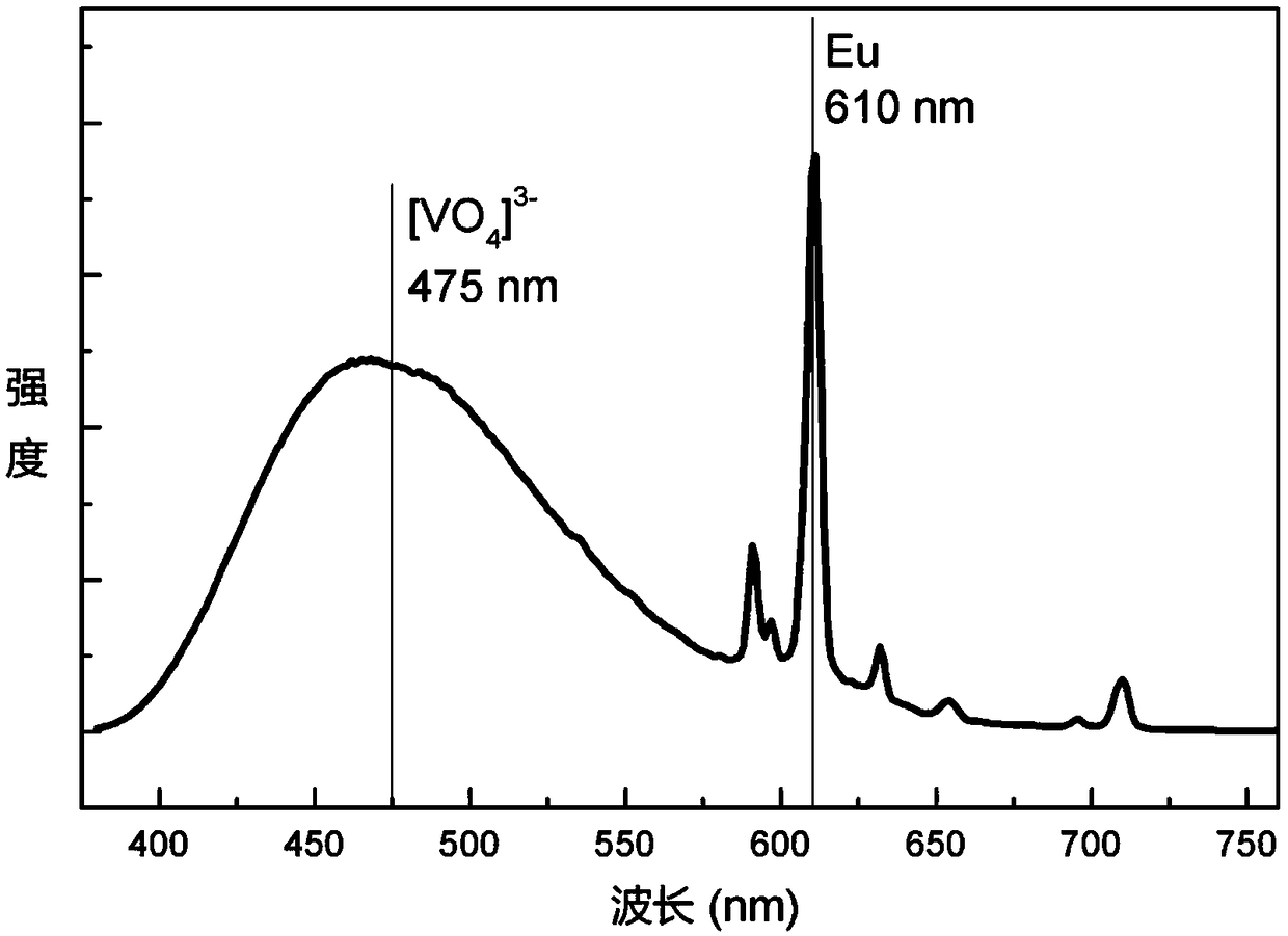
[0030] Weigh calcium carbonate (CaCO 3 ) 3.0006g, lithium carbonate (Li 2 CO 3 ) 0.3695g, ammonium metavanadate (NH 4 VO 3 ) 3.5093g, zinc oxide (ZnO) 0.8141g, and europium oxide (Eu 2 o 3 ) 0.0035g, the above-mentioned raw materials are fully ground and mixed in a mortar, then placed in a corundum crucible, baked in a high-temperature furnace at 1000 ° C for 2 hours, cooled to room temperature, taken out, and after grinding and dispersing, the composition is Ca 2.998 Sr 0.00 ZnLi(VO 4 ) 3 :Eu 0.002 3+ optical temperature measurement materials.

[0031] Excitation and emission tests were carried out on the optical temperature measurement material with a Hitachi F-7000 fluorescence spectrometer, and a 150W xenon lamp was used as the excitation light source. The results show that the material has good absorption in the ultraviolet light band and can be effectively excited by ultraviolet light . Under the effective excitation of ultraviolet light, the [VO 4 ] 3- gro...

Embodiment 2

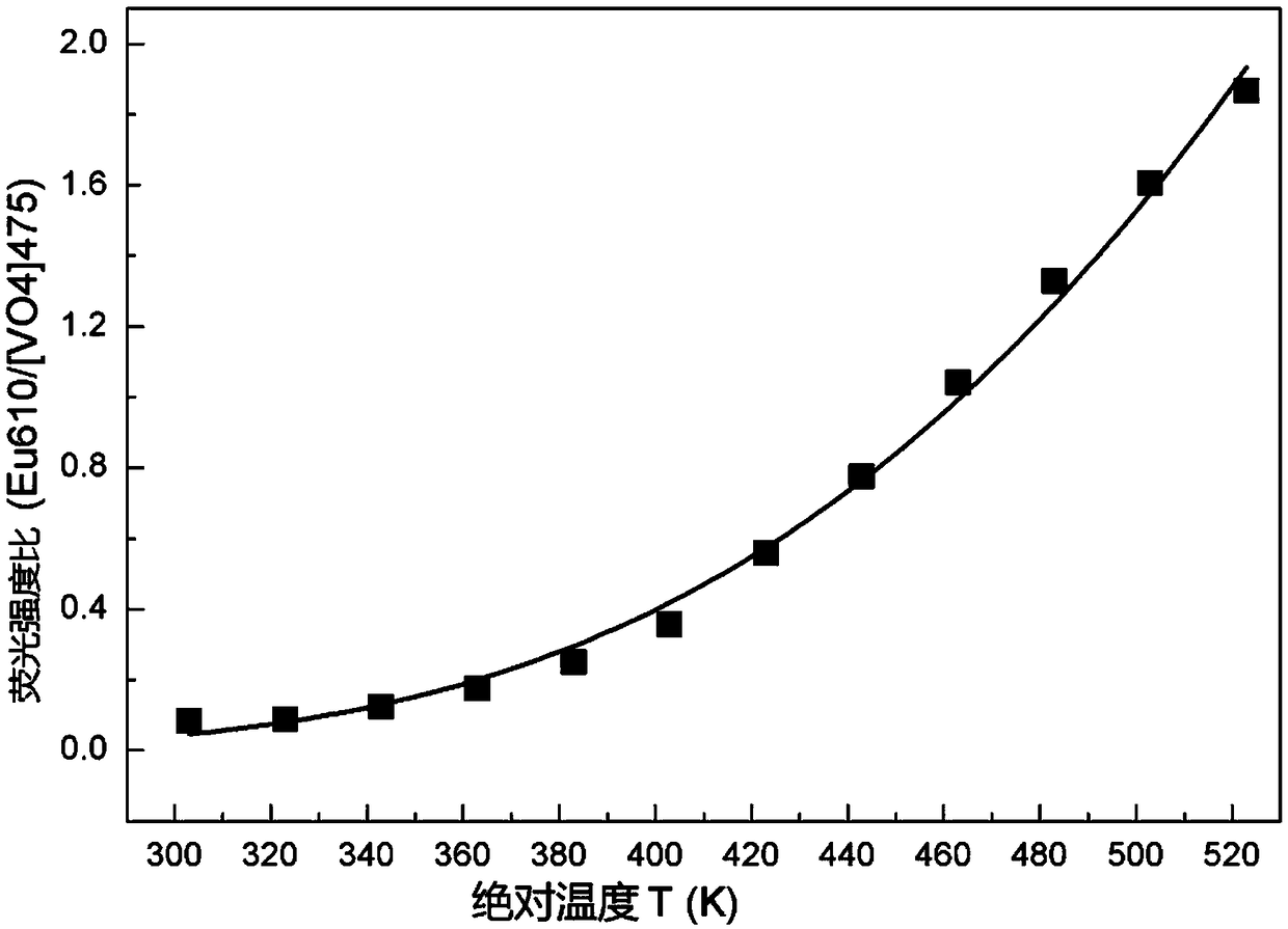
[0033] Weigh respectively calcium oxide (CaO) 1.6795g, lithium oxide (Li 2 O) 0.1494g, vanadium pentoxide (V 2 o 5 ) 2.7282g, zinc hydroxide (Zn(OH) 2 )0.9942g, and europium oxide (Eu 2 o 3 ) 0.0088g, the above-mentioned raw materials were fully ground and mixed in a mortar, then placed in a corundum crucible, baked in a high-temperature furnace at 900°C for 3 hours, cooled to room temperature, taken out, and after grinding and dispersing, the composition Ca 2.995 Sr 0.00 ZnLi(VO 4 ) 3 :Eu 0.005 3+ optical temperature measurement materials. In this way, the temperature can be roughly qualitatively calibrated by using the fluorescence color change, and the temperature can be precisely quantitatively calibrated by using the fluorescence intensity ratio.

Embodiment 3

[0035] Weigh calcium hydroxide (Ca(OH) 2 ) 2.2172g, lithium hydroxide (LiOH) 0.2395g, ammonium metavanadate (NH 4 VO 3 ) 3.5093g, zinc carbonate (ZnCO 3 ) 1.2542g, and europium oxide (Eu 2 o 3 ) 0.0132g, the above-mentioned raw materials were fully ground and mixed in a mortar, then placed in a corundum crucible, baked in a high-temperature furnace at 800°C for 4 hours, cooled to room temperature, taken out, and after grinding and dispersing, the composition Ca 2.9925 Sr 0.00 ZnLi(VO 4 ) 3 :Eu 0.0075 3+ optical temperature measurement materials. In this way, the temperature can be roughly qualitatively calibrated by using the fluorescence color change, and the temperature can be precisely quantitatively calibrated by using the fluorescence intensity ratio.


PUM


Abstract

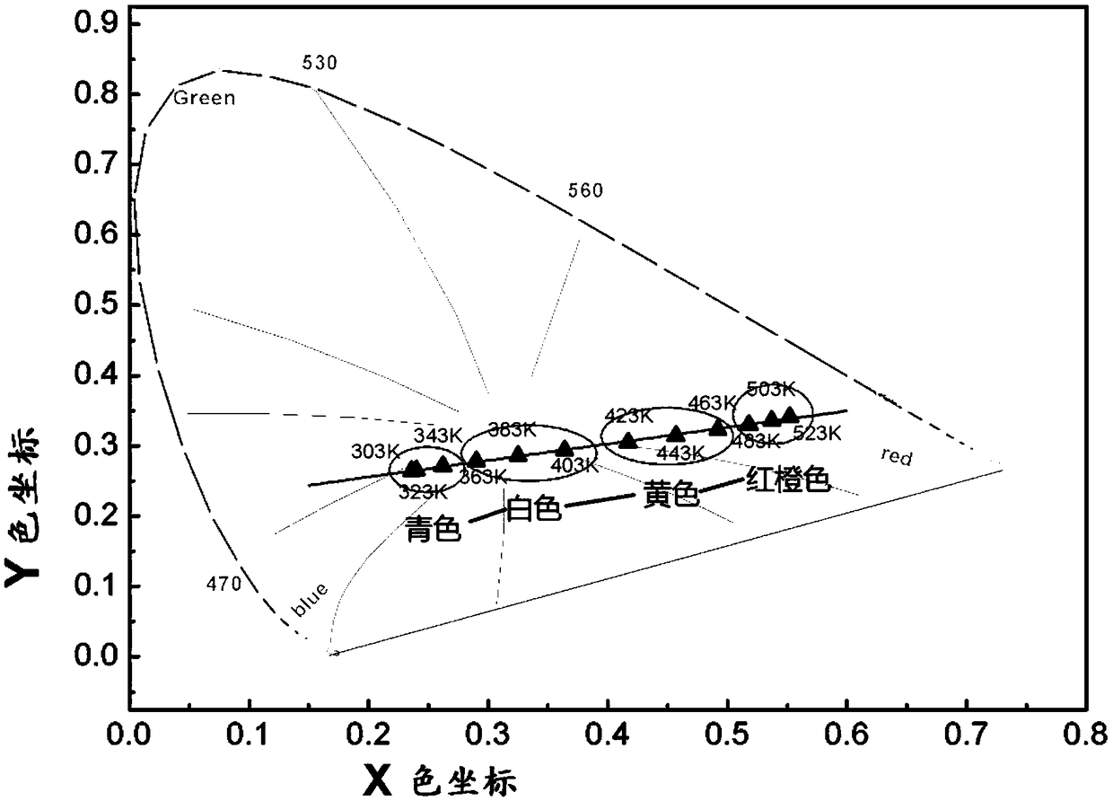
The invention provides an optical temperature measuring material with color-change fluorescence. The structural general formula of the optical temperature measuring material is Ca<3-m-n>Sr<m>ZnLi(VO<4>)<3>:Eu<n><3+>, wherein Eu<n><3+> is an activated ion. The material is prepared by adopting a high-temperature solid-phase method. According to the material, under effective excitation of ultravioletlight, [VO4]<3-> groups of a matrix and activated ion Eu<n><3+> are used as double light-emitting centers to simultaneously give out respective characteristic spectrums. Due to the fact that the thermal quenching properties of the two light emitting centers are different, the change, along with the temperature change, of color coordinates (x,y) corresponding to light emitting colors of the material meets a linear equation trajectory, so that a temperature can be roughly determined and calibrated by utilizing fluorescence color change under excitation of ultraviolet light. Meanwhile, the two characteristic spectrums are monitored, and the temperature is precisely determined and calibrated by utilizing the fluorescence intensity ratio of the double light-emitting centers. Compared with theprior art, the method can be used to roughly calibrate the temperature by utilizing fluorescence color change, and can be used to precisely calibrate the temperature by utilizing the fluorescence intensity ratio of the double light-emitting centers, the temperature measuring range is wide, and the signal detection and discrimination degree is large. The invention further provides a preparation method and application of the optical temperature measuring material with color-change fluorescence.

Description

technical field [0001] The invention belongs to the field of optical temperature-measuring materials, and in particular relates to a fluorescent color-changing optical temperature-measuring material and a preparation method and application thereof. Background technique [0002] Fluorescence intensity ratio technology is applied to temperature sensing, which is a promising optical temperature sensing technology. Compared with the temperature measurement scheme of absolute luminous intensity, measuring the fluorescence intensity ratio can effectively avoid measurement errors caused by factors such as fluorescence loss and excitation light source strength during the measurement process. Among them, the most representative one is the fluorescence intensity ratio temperature measurement scheme based on the thermal coupling energy level of a single rare earth luminescent ion. For the thermal coupling energy level fluorescence intensity ratio temperature measurement technology, to...

Claims


Application Information

Patent Timeline
Patent Type & Authority Applications(China)
IPC IPC(8): C09K11/69G01K11/32
CPCG01K11/32C09K11/7736
Inventor 郭宁宋悦悦潘颖周慧涛丁宇梁启蒙欧阳瑞镯缪煜清
Owner UNIV OF SHANGHAI FOR SCI & TECH
Learn More